Opamp Applications: Peak Detectors, Absolute Value, Comparators
advertisement
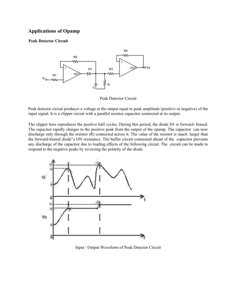
Applications of Opamp Peak Detector Circuit Peak Detector Circuit Peak detector circuit produces a voltage at the output equal to peak amplitude (positive or negative) of the input signal. It is a clipper circuit with a parallel resistor-capacitor connected at its output. The clipper here reproduces the positive half cycles. During this period, the diode D1 is forward- biased. The capacitor rapidly charges to the positive peak from the output of the opamp. The capacitor can now discharge only through the resistor (R) connected across it. The value of the resistor is much larger than the forward-biased diode‟s ON resistance. The buffer circuit connected ahead of the capacitor prevents any discharge of the capacitor due to loading effects of the following circuit. The circuit can be made to respond to the negative peaks by reversing the polarity of the diode. Input / Output Waveform of Peak Detector Circuit Absolute Value Circuit It is the configuration of opamp that produces at its output a voltage equal to the absolute value of the input voltage. The circuit shown above is the dual half wave rectifier circuit. When the applied input is of positive polarity (+V), diode D1 is forward biased and diode D2 is reverse biased. The output (Vo) in this case is equal to +V. When the applied input is of negative polarity (-V), diode D1 is reverse biased and diode D2 is forward biased. By applying Kirchoff‟s Current Law (KCL) at the inverting terminal of the opamp, we can determine voltage (Vx) to be equal to æç 2 ö÷ V. Also, Vx is related to Vo by Vx = æç 2 ö÷ Vo. This implies that Vo = è3 ø è3 ø V. Thus the output always equals the absolute value of the input signal. Comparator Non-inverting comparator with positive refrence and negative reference A comparator circuit is a two input, one-output building block that produce a high or low output depending upon the relative magnitudes of the two inputs. An opamp can be very conveniently used as a comparator when used without negative feedback. Because of very large value of open-loop voltage gain, it produces either positively saturated or negatively saturated output voltage depending upon whether the amplitude of the voltage applied at the non-inverting terminal is more or less positive than the voltage applied at the inverting input terminal. In general, reference voltage voltage may be a positive or a negative voltage. In the above figure, noninverting comparator with a positive reference voltage, VREF is given by +VCC ´ éêêëR 1 R+ 2R 2 úùúû In the above figure, in the case of non-inverting comparator with a negative reference voltage, VREF is given by -VCC ´ éêêëR 1 R+ 2R 2 úùúû


