Physics 427 Lab # 5
advertisement
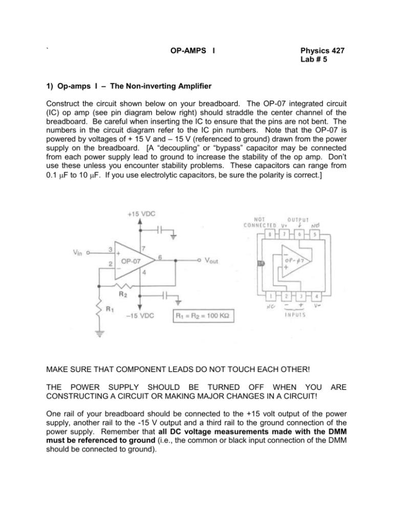
` OP-AMPS I Physics 427 Lab # 5 1) Op-amps I – The Non-inverting Amplifier Construct the circuit shown below on your breadboard. The OP-07 integrated circuit (IC) op amp (see pin diagram below right) should straddle the center channel of the breadboard. Be careful when inserting the IC to ensure that the pins are not bent. The numbers in the circuit diagram refer to the IC pin numbers. Note that the OP-07 is powered by voltages of + 15 V and – 15 V (referenced to ground) drawn from the power supply on the breadboard. [A “decoupling” or “bypass” capacitor may be connected from each power supply lead to ground to increase the stability of the op amp. Don’t use these unless you encounter stability problems. These capacitors can range from 0.1 F to 10 F. If you use electrolytic capacitors, be sure the polarity is correct.] MAKE SURE THAT COMPONENT LEADS DO NOT TOUCH EACH OTHER! THE POWER SUPPLY SHOULD BE TURNED OFF WHEN YOU CONSTRUCTING A CIRCUIT OR MAKING MAJOR CHANGES IN A CIRCUIT! ARE One rail of your breadboard should be connected to the +15 volt output of the power supply, another rail to the -15 V output and a third rail to the ground connection of the power supply. Remember that all DC voltage measurements made with the DMM must be referenced to ground (i.e., the common or black input connection of the DMM should be connected to ground). Construct the voltage divider circuit shown here. It will be used to provide DC input voltage to the op amp. Connect point P of the potentiometer to V in of the amplifier. The gain of the amplifier you have constructed should be 2 as shown by the following: GAIN = 1 + R2/R1 = 1 + 100K/100K = 1 + 1 = 2 Since Vout = GAIN x Vin, the output voltage should be two times the input voltage. In addition, the output voltage should have the same sign as the input voltage (i.e., if the input voltage is positive, the output voltage should be positive). [The actual gain of the amplifier will not be exactly 2 unless the resistors are exactly equal. Measure the actual resistances of R1 and R2 and calculate the true theoretical gain of your amplifier.] a) DC behavior Use the potentiometer to apply a variety of DC voltages to V in (use at least 20 input voltages evenly spaced between +10.0 and –10.0 Volts.) [Note: Don’t change the power supply settings. Simply turn the potentiometer dial to change input voltages.] Measure both Vout and Vin with the DMM (the oscilloscope is not accurate enough) and calculate the measured gain (GAIN = V out/Vin). Does the measured gain agree with the theoretical gain (1+R2/R1)? (Be sure to use the measured values of R2 and R1 in this calculation.) What are the maximum positive and negative output voltages that can be attained? Select R1 and R2 values to give a gain of 5.0. Be sure that R1 is greater than or equal to 1 k and that R2 is no larger than 1M. Measure the gain of the amplifier (you only need to use a single Vin setting for this). How close is the measured gain to the theoretical gain? Repeat for a gain of 101. (Vout may contain a certain amount of noise. This is normal for a high gain amplifier. We will consider noise and how to get rid of it in a later lab.) b) AC behavior Now, we will see how the amplifier responds to AC voltages. As shown in the circuit below, connect the Function Generator to Vin (you do not need to totally rebuild the opamp circuit, just disconnect the input that previously came from the potentiometer and change the resistors) and use both channels of the DSO to measure Vin and Vout. Use R2 = 100K and R1 = 10K (What is the theoretical gain of this amplifier?) [Note that, although the power supply connections are not shown in the above circuit, they still need to be made.] Set the FG to produce a 200 Hz sine wave. Set the amplitude to zero. The dB button should be in the out (the -30dB) position. The DSO should be set to display both channels. Now increase the amplitude of the FG until Vin equals 100 millivolts zero-to-peak (all AC amplitudes in this section will be measured zero-to-peak). What is the amplitude of Vout? Is the AC gain of the circuit the same as the DC gain? You may be having difficulty obtaining a stable DSO display. If so, use an external trigger by connecting a cable from the DSO external input jack to the TTL output of the FG. On the trigger menu, choose ext and edge triggering. Use at least 10 input voltages with zero-to-peak amplitudes spaced evenly between 0.0 and 1.0 volts and see if the gain remains constant (the dB button of the FG should be in the in position). How does the phase of Vout compare to that of Vin? Increase Vin until Vout begins to distort. Sketch the distortion that occurs. At what V out values (positive and negative) does the distortion first start to appear?


