Alternate pathways - Curriculum Support
advertisement
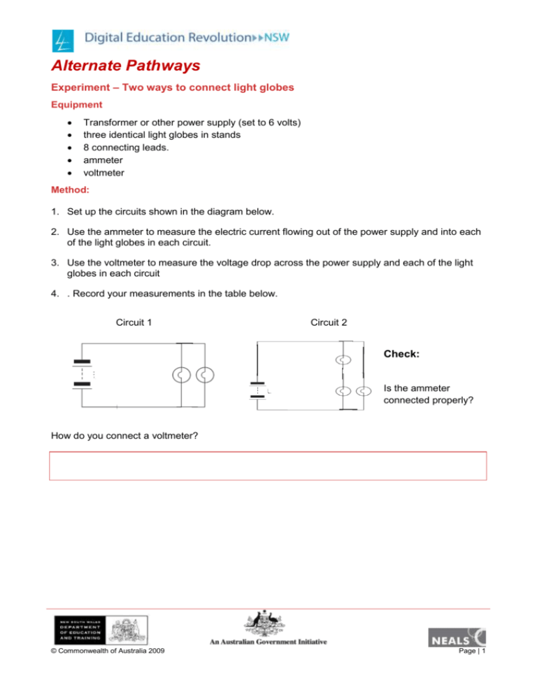
Alternate Pathways Experiment – Two ways to connect light globes Equipment Transformer or other power supply (set to 6 volts) three identical light globes in stands 8 connecting leads. ammeter voltmeter Method: 1. Set up the circuits shown in the diagram below. 2. Use the ammeter to measure the electric current flowing out of the power supply and into each of the light globes in each circuit. 3. Use the voltmeter to measure the voltage drop across the power supply and each of the light globes in each circuit 4. . Record your measurements in the table below. Circuit 1 Circuit 2 Check: Is the ammeter connected properly? How do you connect a voltmeter? © Commonwealth of Australia 2009 Page | 1 Results: Component Circuit 1 Circuit 2 Current (mA) Component Globe X Globe X Globe Y Globe Y Power Supply Power Supply Globe X Globe X Globe Y and Z Globe Y Power Supply Globe Z Voltage (V)) Globe Y and Z Take photos, using the webcam or other device capable of taking a digital photograph, to show the two circuits when turned on. Insert and label the photos as Circuit 1 and Circuit 2 and insert them here. Answer these questions in full sentences. Type your answers in the text boxes. 1. What is the sum of the currents flowing through globes X and Y in circuit 1? © Commonwealth of Australia 2009 Page | 2 2. What happens to the electric current flowing from the power supply when it meets a 'fork' in the pathway? 3. In circuit 2, how does the voltage drop across globes Y and Z compare with the voltage drop across globe X? Explain why this is the case. In Circuit 1 the two light globes are on separate pathways – this is called a parallel circuit. In Circuit 2 the two light globes Y and Z are on the same pathway – this is called a series circuit. Make a general statement about electric current flowing through light globes connected in parallel. 4. Make a general statement about voltage drops across light globes connected in parallel. 5. Re-label the diagrams of circuit 1 and circuit 2 above to highlight the components in series and the components in parallel. Write captions for the diagrams to clearly state the difference in brightness of the light globes in each circuit. When you have completed this activity, email the completed MS Word document to your teacher. Its file name must be your first initial then your last name and date in the following format: jsmith090809 © Commonwealth of Australia 2009 Page | 3


