Franck-Hertz experiment
with Hg-tube
TEP
5.1.03
-11
Related Topics
Energy quanta, quantum jumps, electron collision, excitation energy, Bohr’s shell model
Principle
Electrons are accelerated in a tube filled with mercury vapour. The excitation energy of mercury is determined from the distance between the equidistant minima of the electron current in a variable opposing
electric field.
Equipment
1
1
1
1
1
1
1
1
Franck-Hertz operating unit
Franck-Hertz Hg-tube on plate
Franck-Hertz oven
NiCr-Ni thermocouple
5-pin connecting cable, for Hg-tube
Shielded BNC-cable, l = 75 cm
RS 232 data cable
Franck-Hertz software
09105.99
09105.10
09105.93
13615.01
09105.30
07542.11
14602.00
14522.61
PC, Windows® 95 or higher
Additional equipment:
1 Oscilloscope, 30 MHz, 2 channels
2 Adapter, BNC-socket/4mm plug pair
2 Screened cable, BNC, l = 75 cm
11459.95
07542.27
07542.11
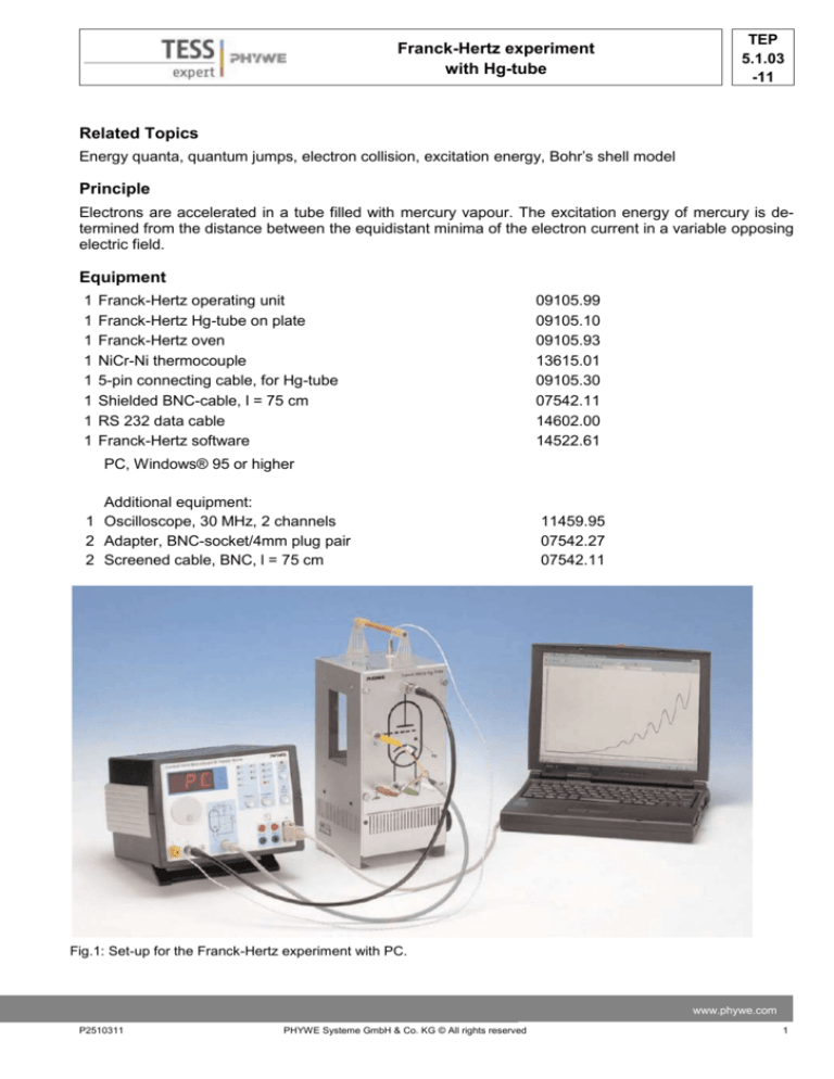
Fig.1: Set-up for the Franck-Hertz experiment with PC.
www.phywe.com
P2510311
PHYWE Systeme GmbH & Co. KG © All rights reserved
1
TEP
5.1.0311
Franck-Hertz experiment
with Hg-tube
Tasks
Record the countercurrent strength I in a Franck-Hertz tube as a function of the anode voltage U. Determine the excitation energy E from the positions of the current strength minima or maxima by difference formation.
Set-up and procedure
Set up the experiment as shown in Fig. 1. For details see the operating instructions of the unit
09105.99. Connect the operating unit to the computer port COM1, COM2 or to USB port (use USB
to RS232 Adapter Converter 14602.10). Start the
measure program and select Cobra3 Franck-Hertz
experiment Gauge. The window “Frank-Hertzexperiment – measuring” (see Fig. 2) appears. The
optimum parameters are different for each Hg-tube.
You find the specific parameters for your device on
a sheet which is enclosed in the package of the Hgtube. Choose the parameters for U1, U2 and UH as
given on that sheet and make sure that the rest is
set as shown in Fig. 2. Press the continue button. Fig. 3: Principle of the measurement.
Now the oven of the Franck-Hertz tube will be
heated to 175 °C. Wait another 30 min before starting the measurement to make sure that the interior of the tube reaches its final temperature, too. At a
particular voltage U1 = UZ, which is dependent on temperature, a glow discharge between anode and
cathode occur through ionisation. Meaningful measurements can therefore only be taken at voltages U1
< UZ.
Fig. 2: Measuring parameters.
2
PHYWE Systeme GmbH & Co. KG © All rights reserved
P2510311
Franck-Hertz experiment
with Hg-tube
TEP
5.1.03
-11
Theory and evaluation
Niels Bohr introduced the planetary model of the atom in 1913: An isolated atom consists of a positively
charged nucleus about which electrons are distributed in successive orbits. He also postulated that only
those orbits occur for which the angular momentum of the electron is an integral multiple of h/2π, i.e.
n*h/2π, where n is an integer and h is Planck’s constant. Bohr’s picture of electrons in discrete states
with transitions among those states producing radiation whose frequency is determined by the energy
differences between states can be derived from the quantum mechanics which replaced classical mechanics when dealing with structures as small as atoms. It seems reasonable from the Bohr model that
just as electrons may make transitions down from allowed higher energy states to lower ones, they may
be excited up into higher energy states by absorbing precisely the amount of energy representing difference between the lower and higher states. James Franck and Gustav Hertz showed that this was, indeed, the case in a series of experiments reported in 1913, the same year that Bohr presented his model. Franck and Hertz used a beam of accelerated electrons to measure the energy required to lift electrons in the ground state of a gas of mercury atoms to the first excited state.
The electrons emitted by a thermionic cathode are accelerated between cathode C and anode A in the
tube filled with mercury vapour (Fig. 3) and are scattered by elastic collision with mercury atoms. From
an anode voltage U1 of 4.9 V, however, the kinetic energy of the electrons is sufficient to bring the valence electron of the mercury to the first excitation level 6 3P1 by an inelastic collision. Because of the
accompanying loss of energy, the electron can now no longer traverse the opposing field between anode
A and counter electrode S: the current I is at a minimum. If we now increase the anode voltage further,
the kinetic energy of the electron is again sufficient to surmount the opposing field: the current strength I
increases. When U1 = 2x4.9 V the kinetic energy is so high that two atoms in succession can be excited
by the same electron: we obtain a second minimum (Fig. 4). The graph of I/U1 thus shows equidistant
maxima and minima. These minima are not, however, very well-defined because of the initial thermal
distribution of the electron velocities. The voltage U1 between anode and cathode is represented by
𝑈1 = 𝑈 + (ΦA − ΦC )
where U is the applied voltage, and A and C the work function voltages of the anode and cathode respectively. As the ecxitation energy E is determined from the voltage differences at the minima, the work
function voltages are of no significance here.
According to the classical theory the energy levels to which the mercury atoms are excited could be random. According to the quantum theory, however, a definite energy level must suddenly be assigned to
the atom in an elementary process. The course of the I/UA curve was first explained on the basis of this
view and thus represents a confirmation of the quantum theory.
The excited mercury atom again releases the energy it has absorbed, with the emission of a photon.
When the excitation energy E is 4.9 eV, the wavelength of this photon is
𝜆=
𝑐ℎ
= 253 𝑛𝑚
𝐸
where c = 2.9979 · 108
𝑚
𝑠
and h = 4.136 · 10-15 eV and thus lies in the UV range.
For our evaluation we determine the voltage values of the minima. From the differences between these
values we obtain the excitation energy E of the mercury atom by taking an average. By evaluating the
measurements in Fig. 4 we obtained the value
E = (4.86 ± 0.09) eV.
www.phywe.com
P2510311
PHYWE Systeme GmbH & Co. KG © All rights reserved
3
TEP
5.1.0311
Franck-Hertz experiment
with Hg-tube
Fig. 4: Example of a Franck-Hertz curve recorded with T = 175°C and U2 = 2 V.
Notes
-
-
-
-
4
Generally speaking the first minima are easier to observe at low temperatures. On the other hand, we
obtain a larger number of minima at higher temperatures, as the ignition voltage of the tube is raised
to higher values.
Due to oven temperature variations slightly different levels of collection current may be obtained for
repeated measurements at the same acceleration voltage. However, the position of the maxima remains unaffected.
When the bimetallic switch switches the oven on and off, there is a change of load on the AC mains,
causing a small change in the set acceleration voltage. This should be noted if the switching takes
place just when the curve is being recorded.
The position of the maxima for the collection current remains unchanged when the reverse bias
changes, but the position of the minima are displaced a little. The level of the mean collection current
decreases with increasing reverse bias.
PHYWE Systeme GmbH & Co. KG © All rights reserved
P2510311

