Michelson Interferometer kim
advertisement
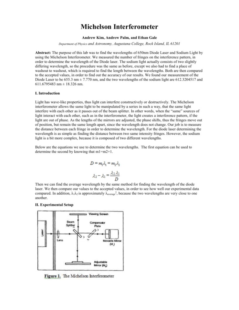
Michelson Interferometer Andrew Kim, Andrew Palm, and Ethan Gale Department of Physics and Astronomy, Augustana College, Rock Island, IL 61201 Abstract: The purpose of this lab was to find the wavelengths of 650nm Diode Laser and Sodium Light by using the Michelson Interferometer. We measured the number of fringes on the interference pattern, in order to determine the wavelength of the Diode laser. The sodium light actually consists of two slightly differing wavelength, so the procedure was the same as before, except we also had to find a place of washout to washout, which is required to find the length between the wavelengths. Both are then compared to the accepted values, in order to find out the accuracy of our results. We found our measurement of the Diode Laser to be 655.3 nm ± 7.770 nm, and the two wavelengths of the sodium light are 612.3204517 and 611.6795483 nm ± 18.326 nm. I. Introduction Light has wave-like properties, thus light can interfere constructively or destructively. The Michelson interferometer allows the same light to be manipulated by a series in such a way, that the same light interfere with each other as it passes out of the beam splitter. In other words, when the “same” sources of light interact with each other, such as in the interferometer, the light creates a interference pattern, if the light are out of phase. As the lengths of the mirrors are adjusted, the phase shifts, thus the fringes move out of position, but remain the same length apart, since the wavelength does not change. Our job is to measure the distance between each fringe in order to determine the wavelength. For the diode laser determining the wavelength is as simple as finding the distance between two same intensity fringes. However, the sodium light is a bit more complex, because it is composed of two different wavelengths. Below are the equations we use to determine the two wavelengths. The first equation can be used to determine the second by knowing that m1=m2+1. Then we can find the average wavelength by the same method for finding the wavelength of the diode laser. We then compare our values to the accepted values, in order to see how well our experimental data compared. In addition, λ1λ2 is approximately λaverage2, because the two wavelengths are very close to one another. II. Experimental Setup In this experiment, we used the Michelson interferometer, Fig. 1, because the measurements are extremely precise. The purpose of an interferometer is to standardize length on either mirror, because we know since the wavelengths have the same length, they will meet up at the same spot given the total length traveled are the same. However, since we are just looking at the interferometer, all we have to do is to align the beam meaning that the two beams produced have to meet up at the viewing screen. A mirror is adjusted by a little knob measured in microns, the actual path versus the length of the mirror movement is actually 2 to 1, since the light reflected, thus the length of the mirror movements are doubled. Equipment Beam Splitter: It is “silvered” to 50%, meaning that half of the light goes through the glass and half of the light is reflected. Basically, it is coated lightly with silver in such a way that microscopically on the surface there are gaps of non-coated glass, which makes up 50% of the surface area. Compensator Plate: It has the same thickness of the same glass as the beam splitter, however it is not silvered. The purpose of the compensator plate, it because the beam that goes through the beam splitter has to go through the glass three times, just like the reflected light, otherwise it will not be in phase with the reflected light beam. This is due to the nature of light having different polarization states, and a subtle detail is that light needs to be in the same polarization states in order to interfere effectively. Alignment Procedure Step 1 Make the laser beam be parallel with the top of the base and strike the center of Movable Mirror, Fig. 1, and be reflected back into the laser source. Step 2 Take the beam splitter, shown in Fig. 1, and set it 45 degrees to the laser beam. Adjust the splitter until; the laser beam hits the adjustable mirror, shown also in Fig. 1. There should be a pattern that resembles tiger stripes, for both the 650nm and Sodium light. However, for the sodium light you have to look into the light in order to see the tiger stripes, whereas the diode you can have a viewing screen. III. Results We were able to find the average wavelength by repeatedly measuring the distance between 11 consecutive fringes, or 10 wavelengths. The number of trials we were aiming for was 20 each, which we approximately reached that goal. Table 1. The equation used to determine error propagation of the sodium light is because we use the second equation used in the introduction section. , Table 1. Table 2. Table 3. Table 4. Table 1. Shows the trimmed data taken for the diode laser, the accepted value is 650nm Each data is a point is the distance between 10 sets of fringes and measured in microns. In addition, the value of the average needs to be doubled, because the recorded distance is just the movement of the mirror and not the actual distance between. The standard error is adjusted for a single fringe, but still in microns. Thus, when converting for a single fringe and into nanometers, the value we have found is 655.3 nm ± 7.770 nm Table 2. Shows the data for the sodium light, the general notes are exactly the same as Table 1. Meaning that the data is of runs of 10 fringes, recorded in microns, and is the length is the movement of the mirror. The average wavelength we have recorded is 612nm ± 18.326 nm. Table 3. Shows the measure of the washout to washout length, there is only one data point, since the other data point is considered contentious. Regardless there is a sample of one data point, so it is not considered very accurate. We have found that our D is 484.4 microns. Table 4. Shows the percent difference of each of the wavelengths, what we found was that there was a .8% difference in the accepted versus our experimental data of the diode laser, and a 3.85% difference in the wavelengths of the sodium light to the accepted value. The accepted values are 650nm for the diode, 589.6 for λ2, and 589.0 for λ1. Figures Fig. 2. Tiger Stripes. In our experiment we measured the distance between dark fringes. However, since our lab was not totally aligned, we were counting fringes at the edge of the circles. The tiger stripes were much harder to see, because a person had to look directly at the light in order to see the pattern. In addition, the fringes moved very fast per mirror movement, and on data points, thus, lots of trials were contentious, since there could have been an extra fringe affecting the average distance. This strain on measurement is the reason we trim some of our data, if it is off from the other samples by a significant amount and marked as contentious. IV. Discussion We found our measurement of the Diode Laser to be 655.3 nm ± 7.770 nm, and the two wavelengths of the sodium light are 612.3204517 and 611.6795483 nm ± 18.326 nm, and these values feel secure. The percent difference between our experimental and accepted values were very small, .8% and 3.5%, for the diode and sodium light wavelengths, respectively. In addition, the accepted values fell between the margins of error for our experiment, which was good. However, this could have been pure coincidence, considering we only used a sample size of one for the measurement of D. But, whatsoever, the gap between the two wavelengths .64 nm closely resemble the gap of the accepted sodium light wavelengths of .6 nm. References Handout [1] Michelson Interferometer Instruction Manual
