Feecon APH Around-the-Pump Foam System Water Supply
advertisement
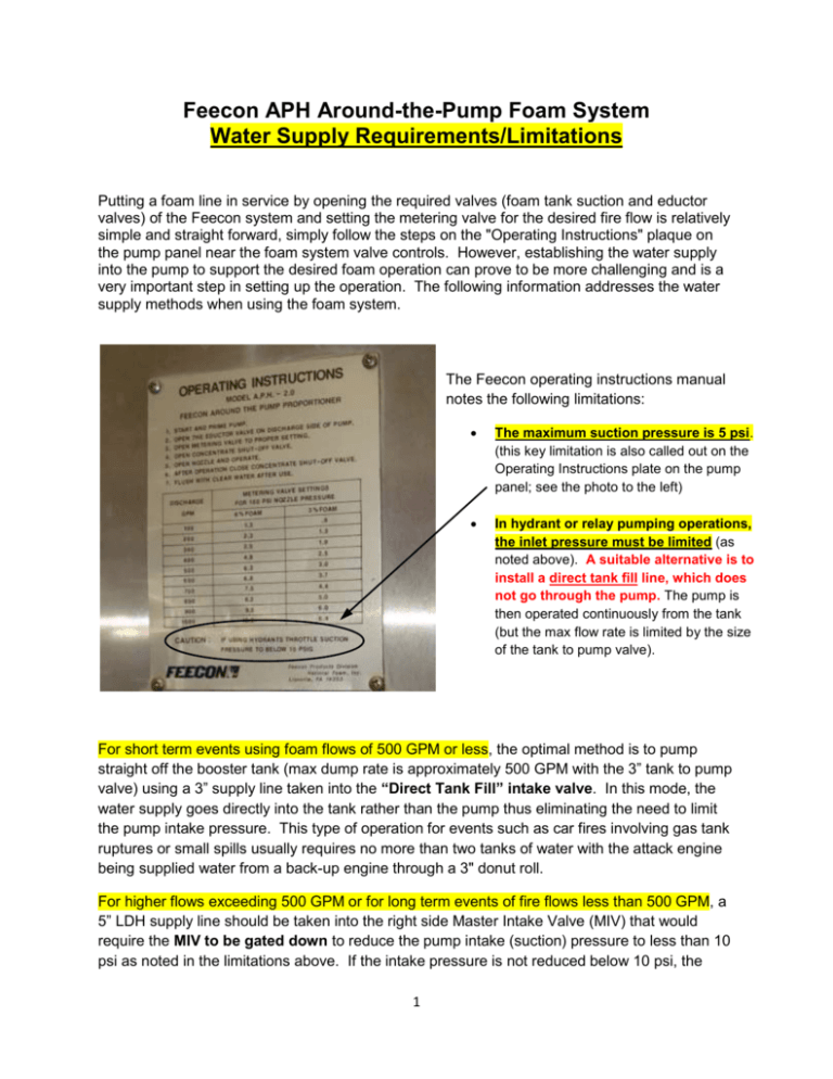
Feecon APH Around-the-Pump Foam System Water Supply Requirements/Limitations Putting a foam line in service by opening the required valves (foam tank suction and eductor valves) of the Feecon system and setting the metering valve for the desired fire flow is relatively simple and straight forward, simply follow the steps on the "Operating Instructions" plaque on the pump panel near the foam system valve controls. However, establishing the water supply into the pump to support the desired foam operation can prove to be more challenging and is a very important step in setting up the operation. The following information addresses the water supply methods when using the foam system. The Feecon operating instructions manual notes the following limitations: The maximum suction pressure is 5 psi. (this key limitation is also called out on the Operating Instructions plate on the pump panel; see the photo to the left) In hydrant or relay pumping operations, the inlet pressure must be limited (as noted above). A suitable alternative is to install a direct tank fill line, which does not go through the pump. The pump is then operated continuously from the tank (but the max flow rate is limited by the size of the tank to pump valve). For short term events using foam flows of 500 GPM or less, the optimal method is to pump straight off the booster tank (max dump rate is approximately 500 GPM with the 3” tank to pump valve) using a 3” supply line taken into the “Direct Tank Fill” intake valve. In this mode, the water supply goes directly into the tank rather than the pump thus eliminating the need to limit the pump intake pressure. This type of operation for events such as car fires involving gas tank ruptures or small spills usually requires no more than two tanks of water with the attack engine being supplied water from a back-up engine through a 3" donut roll. For higher flows exceeding 500 GPM or for long term events of fire flows less than 500 GPM, a 5” LDH supply line should be taken into the right side Master Intake Valve (MIV) that would require the MIV to be gated down to reduce the pump intake (suction) pressure to less than 10 psi as noted in the limitations above. If the intake pressure is not reduced below 10 psi, the 1 Feecon foam system will not function properly preventing the foam concentrate from being injected into the pump through the eductor. Gating the MIV down to limit the intake pressure below 10 psi is however, very sensitive to control and somewhat difficult to setup, even with the electrically operated valve. The MIV can be gated down to reduce the intake pressure to around 5 psi as required but it does take some practice and patience. With the intake valve gated down, there is only a slight loss in the water flow being supplied even at fire flows up to 1000 GPM. To help illustrate the limitations noted above, a flow test was conducted using a Harford County Water System hydrant on Selvin Court off Knollcrest Dr. (Taylor Ridge Development, Box 321). This hydrant has a maximum flow of approx. 2800 GPM with a static pressure of 90 psi. The engine was connected to the hydrant with a 25’ section of 5” LDH taken into the MIV. A fire flow was established through the engine-mounted deck gun equipped with the 2” smooth bore nozzle. The engine discharge pressure was raised using the pressure governor (in the “Pressure” mode) until a measured nozzle pressure of 80 psi (via pitot gauge) was attained providing a flow of approximately 1000 GPM (actual flow of 1063 GPM for a 2” smooth bore nozzle at 80 psi). For informational purposes, the engine discharge pressure was approximately 145 psi (indicated by the master discharge gauge), the flow meter on the pump panel indicated a flow of 1050 GPM for the deck gun, and the pump intake pressure was 70 psi (the hydrant residual pressure for this flow) at this fire flow. With this flow established running off the supply line from the hydrant, the MIV was gated down in an attempt to reduce the pump intake pressure below 10 psi to a target pressure of approximately 5 psi as required if a foam flow was to be established. It was noted that gating down the electrically-controlled MIV butterfly-type valve was not smooth in that the intake pressure would start dropping in large incremental jumps (even when only “bumping” the MIV control lever) rather than gradually descending as the valve was closed down. This made it difficult to get the intake pressure down below 10 psi without closing the valve too much causing the discharge pressure to drop significantly with the fire flow almost totally shutting down. After numerous attempts in gating down the MIV, the pump intake pressure was reduced to approximately 5 psi (holding steady) as indicated on the master intake gauge. With the MIV gated down this amount, the deck gun smooth bore nozzle pitot gauge reading was reduced to 74 psi (down from the 80 psi before the MIV was gated down) yielding a flow of 1023 GPM for the 2” smooth bore nozzle. FYI, the flow meter indicated a flow reading of 1120 GPM at this setting. Gating down the MIV to an intake pressure of 5 psi (down from 70 psi with the valve fully open) only slightly reduced the fire flow from 1063 GPM to 1023 GPM even though the pressure governor was set in the pressure mode. The primary concern is the difficulty in gating down an intake valve, especially for an LDH supply line providing higher flows, to the required intake pressure of less than 10 psi for the foam system to work properly. Gating down the pump intake pressure this much requires several attempts and takes additional time that may not be available on the fire ground. Pump Operators should practice the gating down of an intake valve for operation of the foam system before trying to do it in a real situation. 2 In summary, unless the foam application requires higher fire flows exceeding 500 GPM or for long term events requiring flows less than 500 GPM, it is recommended that flow off the booster tank be used with the supply line taken into the direct tank fill valve. The use of the direct tank fill valve eliminates the need to gate down a regular intake valve to reduce the pump intake pressure as required for the Feecon system. Flowing off the tank limits the max fire flow to 500 GPM due to the size of the tank to pump valve (3”) on the BAVFC engines and rescue truck. However, it should be emphasized that taking a hydrant supply line (likely a 5" LDH line) into the direct tank fill intake will require the operator to constantly monitor the tank water level to prevent the tank from excessively overflowing. This is due to the fact that the water flow into the tank through the 2-1/2" direct tank fill valve can be up to 600 GPM with the intake pressure not exceeding 100 psi (as recommended by the tank manufacturer to prevent possible damage to the tank due to overpressure). Since the fire flow running off the tank cannot exceed 500 GPM, there will likely be a substantially higher flow going into the tank via the direct tank fill valve than is flowing out of the tank into the pump to support the fire flow. As a result, the tank will overflow out through the fill tower (will likely blow open the hinged lid on the fill tower) unless the operator keeps a close watch on the tank water level and closes the direct tank fill valve before the tank completely fills and overflows. The operator will then let the water level in the tank drop with the direct tank fill valve closed until the tank gets low (down to around 1/4 tank remaining) before reopening the valve and taking water back into the tank. The open/close cycling of the direct tank fill intake valve will be required when using a hydrant supply line taken into the direct tank fill to prevent the tank from constantly overflowing. The only other option would be to take the supply line into a regular intake valve such as the MIV which would require the intake valve to be gated down to ensure that the pump intake pressure is no greater than 5 psi as required for the operation of the Feecon foam system. For longer term events, this would prevent the operator from having to constantly monitor the tank water level and having to excessively open/close the direct tank fill valve to keep the tank from overflowing. 3

