ME444-Assignment #6-Sol
advertisement

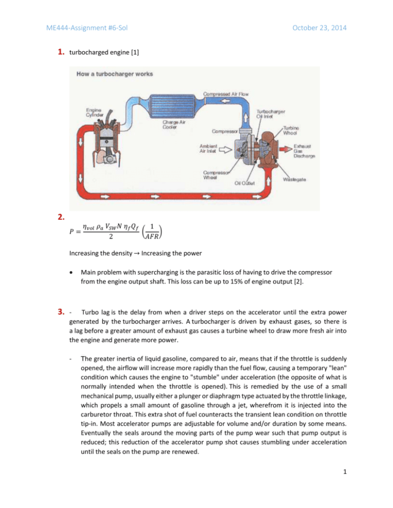
ME444-Assignment #6-Sol 1. October 23, 2014 turbocharged engine [1] 2. 𝑃= 𝜂𝑣𝑜𝑙 𝜌𝑎 𝑉𝑆𝑊 𝑁 𝜂𝑓 𝑄𝑓 1 ( ) 2 𝐴𝐹𝑅 Increasing the density → Increasing the power 3. Main problem with supercharging is the parasitic loss of having to drive the compressor from the engine output shaft. This loss can be up to 15% of engine output [2]. - Turbo lag is the delay from when a driver steps on the accelerator until the extra power generated by the turbocharger arrives. A turbocharger is driven by exhaust gases, so there is a lag before a greater amount of exhaust gas causes a turbine wheel to draw more fresh air into the engine and generate more power. - The greater inertia of liquid gasoline, compared to air, means that if the throttle is suddenly opened, the airflow will increase more rapidly than the fuel flow, causing a temporary "lean" condition which causes the engine to "stumble" under acceleration (the opposite of what is normally intended when the throttle is opened). This is remedied by the use of a small mechanical pump, usually either a plunger or diaphragm type actuated by the throttle linkage, which propels a small amount of gasoline through a jet, wherefrom it is injected into the carburetor throat. This extra shot of fuel counteracts the transient lean condition on throttle tip-in. Most accelerator pumps are adjustable for volume and/or duration by some means. Eventually the seals around the moving parts of the pump wear such that pump output is reduced; this reduction of the accelerator pump shot causes stumbling under acceleration until the seals on the pump are renewed. 1 ME444-Assignment #6-Sol October 23, 2014 4. Hardware Solutions: - Twin-turbo (2 in sequence or parallel) or Twin-scroll turbos - Lighter (but still strong) materials Software Solutions: - At engine speeds below 1800-2200 RPM, when driver commands acceleration through the pedal, create a higher flow and enthalpy than generated by standard fueling strategies, and so raise turbine speed more quickly to reduce lag. The procedure is called Scavenging and provides more air flow than needed to generate requested torque. Of course there is a need to additional fuel to be burnt after combustion. Extra air and fuel burn, generating heat but not torque [1]. One need to be concerned about harming the three-way catalyst by employing the software solution since three-Way Catalytic Converters (“Three-Way Catalysts”, “TWC”) are generally effective at achieving significant reductions of Carbon Monoxide, Hydrocarbons and Nitrogen Oxides. Unfortunately, the operating conditions to which Three-Way Converters are subjected often cause their catalysts to become thermally, chemically and/or mechanically deactivated. These causes of deactivation may occur separately or in combination, but their net effect is always the removal of active sites from the converter’s catalytic surface. One of these causes is thermal deactivation. Thermal degradation of a Three-Way Catalyst begins at temperatures between 800° - 900° C, or in some cases, at lower temperatures depending upon the catalytic material. Thermal degradation is a physical process which leads to catalytic deactivation at high temperatures [3]. 5. Every new car, and most cars produced after 1980, have an oxygen sensor. The sensor is part of the emissions control system and feeds data to the engine management computer. The goal of the sensor is to help the engine run as efficiently as possible and also to produce as few emissions as possible. A gasoline engine burns gasoline in the presence of oxygen. It turns out that there is a particular ratio of air and gasoline that is "perfect," and that ratio is 14.7:1 (different fuels have different perfect ratios -- the ratio depends on the amount of hydrogen and carbon found in a given amount of fuel). If there is less air than this perfect ratio, then there will be fuel left over after combustion. This is called a rich mixture. Rich mixtures are bad because the unburned fuel creates pollution. If there is more air than this perfect ratio, then there is excess oxygen. This is called a lean mixture. A lean mixture tends to produce more nitrogen-oxide pollutants, and, in some cases, it can cause poor performance and even engine damage. The oxygen sensor is positioned in the exhaust pipe and can detect rich and lean mixtures. The mechanism in most sensors involves a chemical reaction that generates a voltage. The engine's computer looks at the voltage to determine if the mixture is rich or lean, and adjusts the amount of fuel entering the engine accordingly. The reason why the engine needs the oxygen sensor is because the amount of oxygen that the engine can pull in depends on all sorts of things, such as the altitude, the temperature of the air, the temperature of the engine, the barometric pressure, the load on the engine, etc. When the oxygen sensor fails, the computer can no longer sense the air/fuel ratio, so it ends up guessing. Your car performs poorly and uses more fuel than it needs to [4]. 2 ME444-Assignment #6-Sol 6. October 23, 2014 There are two different approaches to estimate the Barometric pressure based on manifold pressure. 1. Add delta to the manifold pressure, based on operating condition (flow) 𝑃𝑏𝑎𝑟𝑜𝑚𝑒𝑡𝑟𝑖𝑐 = 𝑃𝐼𝑛𝑡𝑎𝑘𝑒 𝑀𝑎𝑛𝑖𝑓𝑜𝑙𝑑 + 𝐷𝑒𝑙𝑡𝑎 𝑃 At different altitudes, but the same flow, different deltas were needed, so the calibration was always a compromise between sea-level and altitude. 2. Considering the compressible flow model through a restriction: 𝑃𝑀𝑎𝑛𝑖𝑓𝑜𝑙𝑑 𝜙( ) 𝑃𝐴𝑡𝑚 √𝑅𝑇𝐴𝑡𝑚 𝑃𝐴𝑡𝑚 𝑚̇𝑖𝑛𝑡𝑎𝑘𝑒 = 𝐴𝐸𝑓𝑓 𝑃𝑀𝑎𝑛𝑖𝑓𝑜𝑙𝑑 F( 𝑃𝐴𝑡𝑚 ( )= 𝑚̇𝑖𝑛𝑡𝑎𝑘𝑒 √𝑅𝑇𝐴𝑡𝑚 𝐴𝐸𝑓𝑓 𝑃𝑀𝑎𝑛𝑖𝑓𝑜𝑙𝑑 𝑃𝑀𝑎𝑛𝑖𝑓𝑜𝑙𝑑 𝑚̇𝑖𝑛𝑡𝑎𝑘𝑒 √𝑅𝑇𝐴𝑡𝑚 ) = 𝐹 −1 ( ) 𝑃𝐴𝑡𝑚 𝐴𝐸𝑓𝑓 𝑃𝑀𝑎𝑛𝑖𝑓𝑜𝑙𝑑 𝑃𝐴𝑡𝑚 = 𝐹2−1 ( 𝑚̇𝑖𝑛𝑡𝑎𝑘𝑒 √𝑅𝑇𝐴𝑡𝑚 ) ∗ 𝑃𝑀𝑎𝑛𝑖𝑓𝑜𝑙𝑑 𝐴𝐸𝑓𝑓 𝑃𝑀𝑎𝑛𝑖𝑓𝑜𝑙𝑑 3 ME444-Assignment #6-Sol October 23, 2014 Reference: [1] ME444 Lectures/I.C. Engine Control System by Dr. Peter M. Olin, Chief Engineer, Advanced Engineering Americas Powertrain Systems [2] ME444 Lectures/Turbocharging the I.C. Engine by Dr. Philip S. Keller, Borg Warner Inc., Engine System Group [3] http://www.ecooptimized.com/index.php/gasoline/80-three-way-catalysts-aging-causes-of-failureand-deactivation-.html [4] http://auto.howstuffworks.com/question257.htm 4


