Supplementary Info_Revised
advertisement
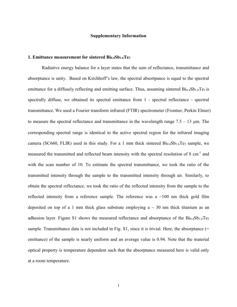
Supplementary Information 1. Emittance measurement for sintered Bi0.4Sb1.6Te3 Radiative energy balance for a layer states that the sum of reflectance, transmittance and absorptance is unity. Based on Kirchhoff’s law, the spectral absortpance is equal to the spectral emittance for a diffusely reflecting and emitting surface. Thus, assuming sintered Bi0.4Sb1.6Te3 is spectrally diffuse, we obtained its spectral emittance from 1 - spectral reflectance - spectral transmittance. We used a Fourier transform infrared (FTIR) spectrometer (Frontier, Perkin Elmer) to measure the spectral reflectance and transmittance in the wavelength range 7.5 – 13 m. The corresponding spectral range is identical to the active spectral region for the infrared imaging camera (SC660, FLIR) used in this study. For a 1 mm thick sintered Bi0.4Sb1.6Te3 sample, we measured the transmitted and reflected beam intensity with the spectral resolution of 8 cm-1 and with the scan number of 10. To estimate the spectral transmittance, we took the ratio of the transmitted intensity through the sample to the transmitted intensity through air. Similarly, to obtain the spectral reflectance, we took the ratio of the reflected intensity from the sample to the reflected intensity from a reference sample. The reference was a ~100 nm thick gold film deposited on top of a 1 mm thick glass substrate employing a ~ 30 nm thick titanium as an adhesion layer. Figure S1 shows the measured reflectance and absorptance of the Bi0.4Sb1.6Te3 sample. Transmittance data is not included in Fig. S1, since it is trivial. Here, the absorptance (= emittance) of the sample is nearly uniform and an average value is 0.94. Note that the material optical property is temperature dependent such that the absorptance measured here is valid only at a room temperature. 1 Figure S1. Measured absorptance and reflectance of a 1 mm thick sintered Bi0.4Sb1.6Te3 at the spectral range of 7.5 – 13 m. Absorptance is obtained by 1 – reflectance, since sintered Bi0.4Sb1.6Te3 is opaque over the corresponding spectral region. An average absorptance over the corresponding spectral region is 0.94. 2 2. Derivation of the modified Harman relation (Eqn. 3) A sum of the energy balances for the cold-side surface and the rest part of the sample is 2ks AT K w TH TC I 2 R PL T T0 L s w I TH TC (S1) (TH + TC)/2 is approximated as 𝑇̅ and TH-TC is ΔT. Then, s w IT ks AT K w T I 2 R PL T T0 L 2 2 2 (S2) We modify Eqn. S2 to obtain (s-w) ΔT. s w 2 k A K I 2 R PL T T0 IT s w T s w 2 2T 2T L (S3) We substitute Eqn. S3 into the relation for Vdc. Vdc IR s w T IR s w 2 IT ks A K w I 2 R PL T T0 L 2 2T 2T w IR s 2 s ks T I s L ks A 1 A L kA K I 2 R PL T T0 s w L 2 2T 2T w IR ZT s i 2 s 2 IR 1 PL2 T T0 KwL I 2 RL 1 2k s A 2Tk s A 2Tk s A (S4) Since IR is equal to either Vac or sL/A, Eqn. S4 can be modified as 2 s w 1 Vdc Vac 1 ZTi PL2 T T0 s KwL I 2 s L2 1 2k s A 2Tk s A2 2Tk s A 3 (S5) Therefore, ZTi can be expressed as V s ZTi dc 1 Vac s w 2 PA T T0 I 2 s L2 K L 1 w 2Tks A2 2ks A 4 (S6) 3. Boundary conditions for the temperature distribution (Eqn. 5) For convenience, define Lh = [ksA/(+h)P]0.5. If the temperature is TH at x = 0 and TC at x = L, TH T 0 c1 c2 I 2 T h PA 0 TC T L c1e L Lh c2e L Lh I 2 T h PA 0 (S7) (S8) An energy balance at x = 0 considers Peltier heating, Joule heating due to electrical contact resistance, conduction heat flow through the sample and lead wires, and convective heat flow from the sample to air. Note that dT/dx = (c1ex/Lh – c2e-x/Lh)/Lh. s w ITH IRc2 ks A c1 c2 K w TH T0 hA TH T0 Lh (S9) Similarly, an energy balance at x = L is expressed as s w ITC IRc2 ks A c1e L Lh c2e L Lh K w T0 TC hA T0 TC Lh (S10) To solve for c1 and c2, we substitute TH in Eqn. S9 by TH in Eqn. S7 and substitute TC in Eqn. S10 by TC in Eqn. S8. Then, we arrange the equations as ks A kA s w I K w hA c1 s s w I K w hA c2 Lh Lh K hA I 2 I 2 s w I T0 w IRc2 (S11) h PA h PA k A k A e L Lh s s w I K w hA c1 e L Lh s s w I K w hA c2 Lh Lh 5 K hA I 2 I 2 s w I T0 w IRc2 h PA h PA c1 and c2 are obtainable by solving Eqn. S11 and S12 via a matrix calculation. 6 (S12)


