Chapter 4. The Yawed Hawt
advertisement
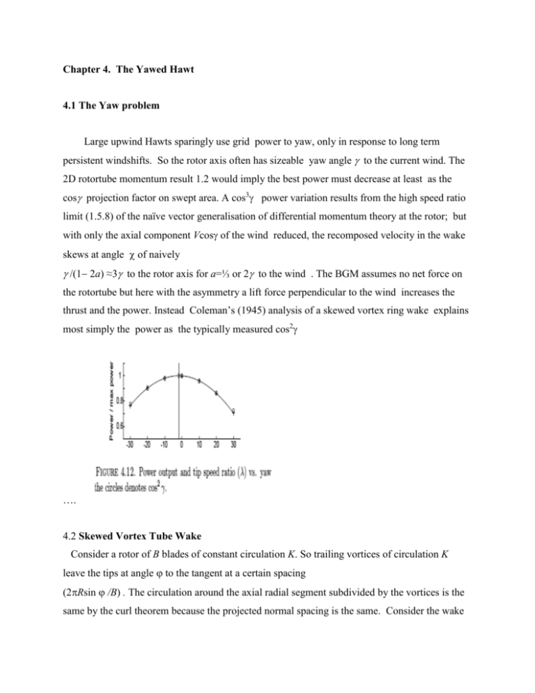
Chapter 4. The Yawed Hawt 4.1 The Yaw problem Large upwind Hawts sparingly use grid power to yaw, only in response to long term persistent windshifts. So the rotor axis often has sizeable yaw angle to the current wind. The 2D rotortube momentum result 1.2 would imply the best power must decrease at least as the cos projection factor on swept area. A cos3 power variation results from the high speed ratio limit (1.5.8) of the naïve vector generalisation of differential momentum theory at the rotor; but with only the axial component Vcos of the wind reduced, the recomposed velocity in the wake skews at angle of naively / 2a) ≈3to the rotor axis for a=⅓ or 2 to the wind . The BGM assumes no net force on the rotortube but here with the asymmetry a lift force perpendicular to the wind increases the thrust and the power. Instead Coleman’s (1945) analysis of a skewed vortex ring wake explains most simply the power as the typically measured cos2 …. 4.2 Skewed Vortex Tube Wake Consider a rotor of B blades of constant circulation K. So trailing vortices of circulation K leave the tips at angle to the tangent at a certain spacing (2Rsin /B) . The circulation around the axial radial segment subdivided by the vortices is the same by the curl theorem because the projected normal spacing is the same. Consider the wake as quickly free of axial vorticity from the blade inner ends by the centrifuging of Chap 1.4., breaking the trailing tip vortices into a series of closed vortex rings, circulation parallel to the rotor and so at angle to the wake separated in time by / B In this interval the (far) wake flow translates the circular rings a skewed distance s down the waketube, s = UaB where Ua is the ultimate average velocity of the rings. The circulation around a path like the one indicated in Fig 4.1 at any azimuth, shows the induced flow component down this solenoid is still uniformly/s, despite the skew. Since the ring (rotor image) planes are separated by normal distance scoshe crosswake component of the velocity jump at the top of the wake cylinder is sin/ scos which should match the potential flow slip of the crosswake - resolution of the outer wind over the top of the elliptic wake cylinder from Batchelor 6.6.21 , sin/scos Vsin(-)(1+1/cos ≈2Vsin(-) (4.2.1) So /≈½/Vs. (4.2.2) Both jump and slip vary sinusoidally with azimuthal angle to then match everywhere. Ring elements of length Rd sticking through the horizontal centerplane plane on the left and right are indistinguishable from unskewed ones so the flow they induce is parallel to the wake centerline. Top and bottom ring elements the same Rd long induce on the centerline an equal speed but perpendicular to their skew . This motivates that the net induced flow is horizontal at angle ‘ ‘ to and at the centerline of ½. As in a normal solenoid , Biot-Savart integration shows this angle is constant throughout the wake. That allows the net U0 of wind plus uniform induced velocity to flow down the waketube as by halving (4.2.1) , the crosswake induced tan / s equals Vsin (-), the crosswake component of the wind. So thus ≈½ or the induced flow bisects the angle between the rotor axis and the wake cylinder it has the same component along each, s =2In say 2aVcos as in the BGM, so (4.2.2) gives ≈/a) (4.2.3) so 3/2 is ½ the naïve value at a=⅓ So the real wake skew to the wind is ≈ a/ a) (4.2.4) or ½ which is a small ¼ the wild naïve BEM value at a=⅓ The mean of the velocities outside and inside the wake cylinder Ua= Vcos(-)-½/s or Ua /V= cos(-)-acos translates the rings, so the ring spacing is s = UaB thus = 2In Ua /B (4.2.5) Exercise: Show that H=Ua/s and Ua≈ (1-a)V (1+2/16) where the last term is evaluated at a=⅓ . So the ring convection speed is hardly unchanged with yaw at a=⅓ . Now the power P from the B blades is BQ/ (from Batchelor 6.6.26) (which automatically rejects spanwise flow) or P=2InUaQ (4.2.6). Ignoring the near wake and its expansion, every point on the rotor at azimuth has a mirror point at + of equal induced vector on the imaginary upstream half of an infinite vortex cylinder, so the average induced flow normal to the rotor must be half the full cylinder 2In. This makes Q=(1-a) VS cos as in the BGM . But now Ua≈ (1-a)V instead of another (1-a) VS cos in the BGM gives the optimum P at a=⅓ to vary a bit less than cos2 as 1-152/16. The change is entirely due to the difference in cos(-) from the BGM coshe component of wind perpendicular to the vortex plane helps convect vorticity along the skewed wake increasing the H. For=0 tangent blades elements =clW sin is on azimuthal average cl V cos (1a) almost perfectly matching the above = acos V Ua / B for Ua/V ≈ (1-a)V for any wind direction to the rotor(The non-dimensional chord Bkl=4a indicates that a changes from optimum linearly with V which is the speed variation non-robustness with tangent blades as in Chapters 2 and 6) Exercise: With the more accurate Ua show the match to second order in a=⅓) at high x would require Bkl=7a/2 and =- (1-a)/ 8x compared with =(1-a)/x. Negative pitch is unusual and with normal positive pitch, the match can’t be sustained, and a would decrease with yaw and the performance would drift below optimum 1-.942 with , such as to the cos2 measured in the Figure 3.12 for a fixed pitch rotor. There must be a tradeoff with robust for well as power average windspeed. The yaw best fixed pitch according to the statistics of statistics would be specific to each design wind speed and direction and yaw and control strategy. Unfortunately even response. Of course the designed optimum wind direction statistics are little studied. should be at the w(V) power average yaw as Exercise: Show that with Ua≈ (1-a)V , designing for robustness at a mean value of yaw o, still gives the design pitch to bisect the design =(1-a)cos o /x at large x but for the vortex theory =2a/lx (whereas for the resolved flow BM =2a cos o /lx) 4.3 Momentum balances, Induced flow variations and Yaw moment The blades axial A thrust BK r per unit span totaling to 2InUaS, (or SH) is higher by the cos factor than the rate of change 2InQ of rotortube momentum along the rotor axis. Also why at high x, is there a component of I in the rotorplane normal to the pressure jumpH across the rotor? The induced flow J and so dQ at the rotor should be symmetric about the page in Fig 4.1 so there should no net blade drive to left or right. These discrepancies indicate a greater pressure on windward side of the rotortube as it passes the rotor than on the leeward side. One force the outer irrotational fluid can exert on the rotortube inside it is a lift 2L perpendicular to V and away from the skew, so it would have a rotor axis component, (half of it momentum flux Batchelor 407). The rotortube momentum balance is then 2Q I=L -A . So taking crossrotor or rotorplane components P≈2InQ tan. Then resp. vortex A and momentum rotor thrust components are 2In times UaS vs Q(1+ tan tan ) =V(1-a)S(1+¼) so L overcorrects the axial momentum balance by a factor of 4/3 at a=⅓ but agreeing as a and the expansion goes to 0 taking to ½.he 3/16 might be taken as an expansion correction to A and the power P=Au for a net 1-¾2 at a=⅓, though this would require even more stall-defying negative pitch to maintain with . At any rate (resolved) momentum theories err in yaw because they generalise from windwise with no drag (Chapter 1.2) to no rotor tube force neglecting the possibility of skewed rotortube lift L normal to the wind. Such a lift requires net vertical vorticity inside the wake tube and the unbalanced leading lip of the vortex rings from the upwind (right) edge of the rotor has the right orientation of K and with its area scaling as R2 its lift scales correctly as O(InUaS The lift also implies net pressure on the rotortube walls and indeed the low pressure backside of the rotor is particularly close to the upwind leading wedge of the waketube. As the pressure varies, the velocity must vary for the uniform H across the rotortube tube indicated by the uniform velocity far upstream and downstream. Indeed the induced flow J on downwind side of the rotor mouth of the vortex tube closer to the rings should be greater than that on the upwind side, but symmetrical about the horizontal. So the leading term in a Taylor series would a linear variation of J from I of J≈ vyR where y is distance to the left of a blade element from the rotor center . Say it spans about say a diameter flow-wise. Then there would be a net Bernoulli lateral force of 2R∫u vsin2 Rd or 2u vR2 on the rotortube to equal 2uS aVcostan thus v≈aVtan so J≈IyR agreeing with Coleman’s direct integration at the rotor for the induction J of unexpanded wake vortex rings. This J variation implies just a variation in local power with no change to the net power, which depends on the uniform But for a physical blade element to have the constant despite the J variation in requires azimuthally varying pitch to maintain constant . Many have violated the constant K in calculating the tangent blade circulation as (c times) V cos (1a) - aVyR with relative variation ayR(1-a) It is more reasonable to generalise the above picture (implicitly with vortex rays shed by the blades) to say that the induced flow J at the rotor is aVy/R more than I , half the induced flow downstream on the same streamline. Then for a tangent blade the circulation varies as (c times) V cos (1-a) -I-aVy/R whilst the now ‘local” resulting induced flow in the wake would vary as 2aV +2I . For these to be proportional requires I to be -a2Vy/R/(1-2a) for relative variation as ay/R at small a, or quibbling aof the naive value. More importantly such variation may still be sufficient to trip a blade from lift enhanced by Coriolos secondary flow (appendix 2) into a deep stall. Exercise: Show this simultaneous variation of K and u reduces the tangent blade power fractionally as the average square of ay/R over the area or /64 at a=⅓ . Show it causes a yaw restoring torque equal to the thrust times the arm ⅜aRabout the rotor center, as if it were directed downwind at a virtual center ⅜aR behind the rotor. How a Hawt actually passively yaws requires analysis of the larger yaw moments of the tailvane with particular attention to any aerodynamic damping. Structurally rapid yaw can impose large gyroscopic moments on the spinning rotor so additional strengthening or damping can be needed. An implication would be that other tangent blade crosswind mills such as the oscillating wing at low wind tolerate yaw as cos2 also. Of course our next major subject the (tangent blade) Vawt is already perfect in yaw.
