HW2
advertisement
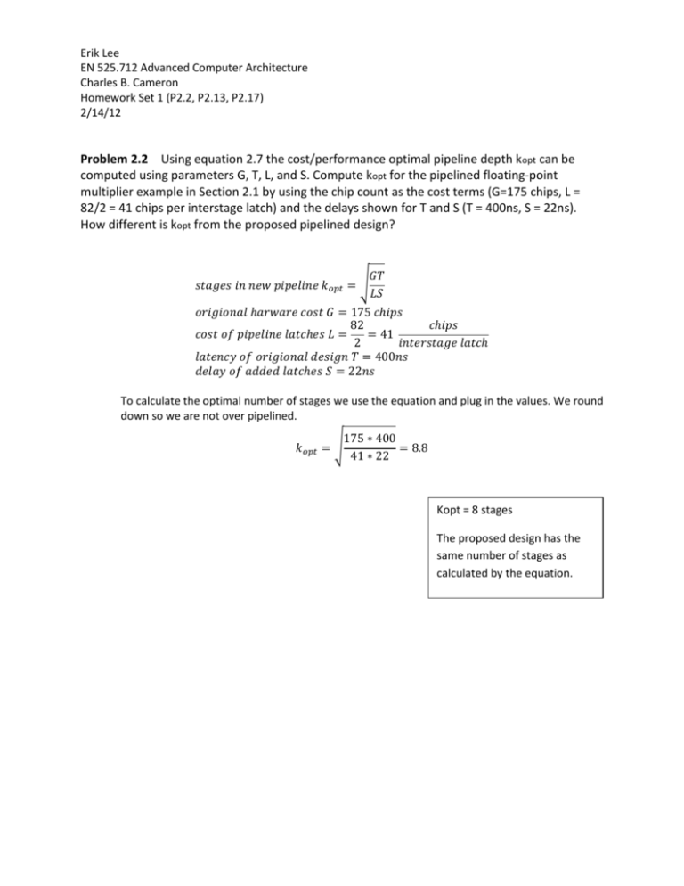
Erik Lee EN 525.712 Advanced Computer Architecture Charles B. Cameron Homework Set 1 (P2.2, P2.13, P2.17) 2/14/12 Problem 2.2 Using equation 2.7 the cost/performance optimal pipeline depth kopt can be computed using parameters G, T, L, and S. Compute kopt for the pipelined floating-point multiplier example in Section 2.1 by using the chip count as the cost terms (G=175 chips, L = 82/2 = 41 chips per interstage latch) and the delays shown for T and S (T = 400ns, S = 22ns). How different is kopt from the proposed pipelined design? 𝐺𝑇 𝑠𝑡𝑎𝑔𝑒𝑠 𝑖𝑛 𝑛𝑒𝑤 𝑝𝑖𝑝𝑒𝑙𝑖𝑛𝑒 𝑘𝑜𝑝𝑡 = √ 𝐿𝑆 𝑜𝑟𝑖𝑔𝑖𝑜𝑛𝑎𝑙 ℎ𝑎𝑟𝑤𝑎𝑟𝑒 𝑐𝑜𝑠𝑡 𝐺 = 175 𝑐ℎ𝑖𝑝𝑠 82 𝑐ℎ𝑖𝑝𝑠 𝑐𝑜𝑠𝑡 𝑜𝑓 𝑝𝑖𝑝𝑒𝑙𝑖𝑛𝑒 𝑙𝑎𝑡𝑐ℎ𝑒𝑠 𝐿 = = 41 2 𝑖𝑛𝑡𝑒𝑟𝑠𝑡𝑎𝑔𝑒 𝑙𝑎𝑡𝑐ℎ 𝑙𝑎𝑡𝑒𝑛𝑐𝑦 𝑜𝑓 𝑜𝑟𝑖𝑔𝑖𝑜𝑛𝑎𝑙 𝑑𝑒𝑠𝑖𝑔𝑛 𝑇 = 400𝑛𝑠 𝑑𝑒𝑙𝑎𝑦 𝑜𝑓 𝑎𝑑𝑑𝑒𝑑 𝑙𝑎𝑡𝑐ℎ𝑒𝑠 𝑆 = 22𝑛𝑠 To calculate the optimal number of stages we use the equation and plug in the values. We round down so we are not over pipelined. 175 ∗ 400 𝑘𝑜𝑝𝑡 = √ = 8.8 41 ∗ 22 Kopt = 8 stages The proposed design has the same number of stages as calculated by the equation. Problem 2.13 Given the IBM experience outlined in Section 2.2.4.3, compute the CPI impact of the addition of a level-zero data cache that is able to supply the data operand in a single cycle, but only 75% of the time. The level-zero and level-one caches are accessed in parallel, so that when the level-zero cache misses, the level-one cache returns the result in the next cycle, resulting in a load-delay slot. Assume uniform distribution of level-zero hits across load-delay slots that can and cannot be filled. Show your Work. There are 3 features that can save a load instruction from penalty. Each can save a single clock cycle. Forwarding hardware saves an instruction cycle for every load instruction. Scheduling will save an instruction another cycle 75% of the time. Finally, by adding the level-0 cache 75% of loads will save another cycle. Forwarding Yes (100%) Yes (100%) Yes (100%) Yes (100%) Scheduled Yes (75%) Yes (75%) No (25%) No (25%) Level zero hit Yes (75%) No (25%) Yes (75%) No (25%) Load penalty 0 Cycles 0 Cycles 0 Cycles 1 Cycles There are 3 features that can save a branch instruction from penalty. Each can save a single clock cycle. Being PC-relative, unconditional, schedulable or a level zero hit each save a clock cycle of penalties. Being an unconditional branch has the same benefit of being schedulable. Unconditional Yes (33%) Yes (33%) Yes (33%) Yes (33%) No (66%) No (66%) No (66%) No (66%) No (66%) No (66%) No (66%) No (66%) PC-Relative Address Yes (90%) Yes (90%) No (10%) No (10%) Yes (90%) Yes (90%) Yes (90%) Yes (90%) No (10%) No (10%) No (10%) No (10%) Scheduled Level zero hit Branch Penalty ----Yes (50%) Yes (50%) No (50%) No (50%) Yes (50%) Yes (50%) No (50%) No (50%) Yes (75%) No (25%) Yes (75%) No (25%) Yes (75%) No (25%) Yes (75%) No (25%) Yes (75%) No (25%) Yes (75%) No (25%) 0 Cycles 0 Cycles 0 Cycles 1 Cycles 0 Cycles 0 Cycles 0 Cycles 1 Cycles 0 Cycles 1 Cycles 1 Cycles 2 Cycles In calculating the penalties for all the scenarios if there are at least two cycles saving features there are no penalties. If there is only one cycle saving feature there is only a one cycle penalty. If there are no cycle saving features there is a two cycle penalty. 𝐶𝑃𝐼 = 1 𝐴𝑙𝑙 𝑜𝑛𝑒 𝑐𝑦𝑐𝑙𝑒 𝑖𝑛𝑠𝑡𝑟𝑢𝑐𝑡𝑖𝑜𝑛 +𝐿𝑜𝑎𝑑 𝑁𝑜𝑡 𝑠𝑐ℎ𝑒𝑑𝑢𝑙𝑒𝑑 𝐿𝑒𝑣𝑒𝑙 𝑧𝑒𝑟𝑜 𝑚𝑖𝑠𝑠(25% ∗ 25% ∗ 25% ∗ 1) +𝐵𝑟𝑎𝑛𝑐ℎ 𝑈𝑛𝑐𝑜𝑛𝑑𝑖𝑡𝑖𝑜𝑛𝑎𝑙 𝑁𝑜𝑡 𝑃𝐶𝑟𝑒𝑙𝑎𝑡𝑖𝑣𝑒 𝐿𝑒𝑣𝑒𝑙 𝑧𝑒𝑟𝑜 𝑚𝑖𝑠𝑠 (20% ∗ 33% ∗ 10% ∗ 25% ∗ 1) +𝐵𝑟𝑎𝑛𝑐ℎ 𝐶𝑜𝑛𝑑𝑖𝑡𝑖𝑜𝑛𝑎𝑙 𝑃𝐶𝑟𝑒𝑙𝑎𝑡𝑖𝑣𝑒 𝑁𝑜𝑡 𝑠𝑐ℎ𝑒𝑑𝑢𝑙𝑒𝑑 𝐿𝑒𝑣𝑒𝑙 𝑧𝑒𝑟𝑜 𝑚𝑖𝑠𝑠 (20% ∗ 66% ∗ 90% ∗ 50% ∗ 25% ∗ 1) +𝐵𝑟𝑎𝑛𝑐ℎ 𝐶𝑜𝑛𝑑𝑖𝑡𝑖𝑜𝑛𝑎𝑙 𝑁𝑜𝑡 𝑃𝐶𝑟𝑒𝑙𝑎𝑡𝑖𝑣𝑒 𝑆𝑐ℎ𝑒𝑑𝑢𝑙𝑒𝑑 𝐿𝑒𝑣𝑒𝑙 𝑧𝑒𝑟𝑜 𝑚𝑖𝑠𝑠 (20% ∗ 66% ∗ 10% ∗ 50% ∗ 25% ∗ 1) +𝐵𝑟𝑎𝑛𝑐ℎ 𝐶𝑜𝑛𝑑𝑖𝑡𝑖𝑜𝑛𝑎𝑙 𝑁𝑜𝑡 𝑃𝐶𝑟𝑒𝑙𝑎𝑡𝑖𝑣𝑒 𝑁𝑜𝑡 𝑆𝑐ℎ𝑒𝑑𝑢𝑙𝑒𝑑 𝐿𝑒𝑣𝑒𝑙 𝑧𝑒𝑟𝑜 ℎ𝑖𝑡 (20% ∗ 66% ∗ 10% ∗ 50% ∗ 75% ∗ 1) +𝐵𝑟𝑎𝑛𝑐ℎ 𝐶𝑜𝑛𝑑𝑖𝑡𝑖𝑜𝑛𝑎𝑙 𝑁𝑜𝑡 𝑃𝐶𝑟𝑒𝑙𝑎𝑡𝑖𝑣𝑒 𝑁𝑜𝑡 𝑆𝑐ℎ𝑒𝑑𝑢𝑙𝑒𝑑 𝐿𝑒𝑣𝑒𝑙 𝑧𝑒𝑟𝑜 𝑚𝑖𝑠𝑠 (20% ∗ 66% ∗ 10% ∗ 50% ∗ 25% ∗ 2) 𝐶𝑃𝐼 = 1 +.25 ∗ .25 ∗ .25 +.20 ∗ .33 ∗ .10 ∗ .25 +.20 ∗ .66 ∗ .90 ∗ .50 ∗ .25 +.20 ∗ .66 ∗ .10 ∗ .50 ∗ .25 +.20 ∗ .66 ∗ .10 ∗ .50 ∗ .75 +.20 ∗ .66 ∗ .10 ∗ .50 ∗ .25 ∗ 2 𝐶𝑃𝐼 = 1.042025 CPI = 1.042025 Problem 2.17 The MIPS pipeline shown in table 2.7 employs a two-phase clocking scheme that makes efficient use of a shared TLB, since instruction fetch accesses the TLB in phase one and data fetch accesses in phase two. However, when resolving a conditional branch, both the branch target address and the branch-fall through address need to be translated during phase one – in parallel with the branch condition check in phase one of the ALU stage – to enable instruction fetch from either the target or the fall-through during phase two. This seems to imply a dual-ported TLB. Suggest an architected solution to this problem that avoids dualporting the TLB. The translation from the TLB for the branch instruction was fetched during the IF2 phase and the RD1 phase. By calculating the next address we know the translated address of the fall through address. The only thing we have to check for is if the instruction is on a boundary. If it is on a boundary then we can incur a penalty and query the TLB for the correct address translation.
