Exercise 2: Basic Electricity Concepts
advertisement
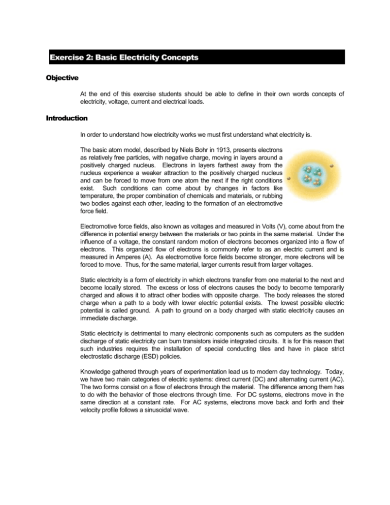
Exercise 2: Basic Electricity Concepts Objective At the end of this exercise students should be able to define in their own words concepts of electricity, voltage, current and electrical loads. Introduction In order to understand how electricity works we must first understand what electricity is. The basic atom model, described by Niels Bohr in 1913, presents electrons as relatively free particles, with negative charge, moving in layers around a positively charged nucleus. Electrons in layers farthest away from the nucleus experience a weaker attraction to the positively charged nucleus and can be forced to move from one atom the next if the right conditions exist. Such conditions can come about by changes in factors like temperature, the proper combination of chemicals and materials, or rubbing two bodies against each other, leading to the formation of an electromotive force field. Electromotive force fields, also known as voltages and measured in Volts (V), come about from the difference in potential energy between the materials or two points in the same material. Under the influence of a voltage, the constant random motion of electrons becomes organized into a flow of electrons. This organized flow of electrons is commonly refer to as an electric current and is measured in Amperes (A). As electromotive force fields become stronger, more electrons will be forced to move. Thus, for the same material, larger currents result from larger voltages. Static electricity is a form of electricity in which electrons transfer from one material to the next and become locally stored. The excess or loss of electrons causes the body to become temporarily charged and allows it to attract other bodies with opposite charge. The body releases the stored charge when a path to a body with lower electric potential exists. The lowest possible electric potential is called ground. A path to ground on a body charged with static electricity causes an immediate discharge. Static electricity is detrimental to many electronic components such as computers as the sudden discharge of static electricity can burn transistors inside integrated circuits. It is for this reason that such industries requires the installation of special conducting tiles and have in place strict electrostatic discharge (ESD) policies. Knowledge gathered through years of experimentation lead us to modern day technology. Today, we have two main categories of electric systems: direct current (DC) and alternating current (AC). The two forms consist on a flow of electrons through the material. The difference among them has to do with the behavior of those electrons through time. For DC systems, electrons move in the same direction at a constant rate. For AC systems, electrons move back and forth and their velocity profile follows a sinusoidal wave. Current Current Time The magnitude of the current in a DC system is constant. Time The magnitude of the current in an AC system follows a sinusoidal wave. AC electricity is somewhat more complex and will be dealt with in a later exercise. For now, let’s focus on DC systems. Voltage sources for DC systems include batteries, solar cells, thermocouples, DC generators and hydrogen cells. Batteries are, by far, the most common type of DC voltage sources used. (The following information is taken from http://science.howstuffworks.com. The site has plenty of additional and interesting information on the subject. Students are urged to visit the site and get the full story.) Battery Basics If you look at any battery, you'll notice that it has two terminals. One terminal is marked (+), or positive, while the other is marked (-), or negative. In an AA, C or D cell (normal flashlight batteries), the ends of the battery are the terminals. In a large car battery, there are two heavy lead posts that act as the terminals. Electrons collect on the negative terminal of the battery. If you connect a wire between the negative and positive terminals, the electrons will flow from the negative to the positive terminal as fast as they can (and wear out the battery very quickly -- this also tends to be dangerous, especially with large batteries, so it is not something you want to be doing). Normally, you connect some type of load to the battery using the wire. The load might be something like a light bulb, a motor or an electronic circuit like a radio. Inside the battery itself, a chemical reaction produces the electrons. The speed of electron production by this chemical reaction (the battery's internal resistance) controls how many electrons can flow between the terminals. Electrons flow from the battery into a wire, and must travel from the negative to the positive terminal for the chemical reaction to take place. That is why a battery can sit on a shelf for a year and still have plenty of power -- unless electrons are flowing from the negative to the positive terminal, the chemical reaction does not take place. Once you connect a wire, the reaction starts. The first battery was created by Alessandro Volta in 1800. To create his battery, he made a stack by alternating layers of zinc, blotting paper soaked in salt water, and silver, like this: This arrangement was known as a voltaic pile. The top and bottom layers of the pile must be different metals, as shown. If you attach a wire to the top and bottom of the pile, you can measure a voltage and a current from the pile. The pile can be stacked as high as you like, and each layer will increase the voltage by a fixed amount. The excerpt above talks about batteries, but also about connecting their terminals to loads using wires. That is called a circuit. When the components are connected so that there is a continuous path for the current to flow between the terminals of the battery, the circuit is known as a closed circuit. An open circuit, on the other hand, would be a circuit in which such a continuous path does not exist. No current flows through open circuits. The term load refers to the device we connect to the circuit. Examples of loads are light bulbs, motors, buzzers, computers, stereos, cell phones, electronic toys, etc. Magnetism Molecules in ordinary metals are polarized. This means that each molecule has a positive and a negative side. Yet, these molecules are randomly arranged so that the overall material is not polarized. The presence of a magnetic field around a metal, however, will cause these molecules to rotate and align with the magnetic field. The end result is a magnet. When an electric current flows through a conductor, it induces a magnetic field around the conductor. It is possible to concentrate the magnetic field by forming a coil with the wire. If such coil is wound around a metal, the metal will become temporarily magnetized. That is known as an electromagnet. Demo 1: Static Electricity (Demo performed by the Instructor) Materials 4” * 2” piece of foam 1 Sheet of tissue paper Procedure 1) Place some small pieces of tissue paper on the table. 2) Rub the foam piece on your hair for a few seconds. 3) Hold the foam close to the tissue pieces. Test 1: Building a battery Materials Multimeter set-up to measure voltage 30 Zinc washers 30 Aluminum washers 30 nickels 30 pennies Small pan or shallow dish 5 sheets of tissue paper Salt Vinegar Try this!! Insert a Zinc nail and a Copper nail into a lime so they are close by, but not touching inside or outside. Touch it with your tongue for the tingly sensation of a current flow. Procedure 1) Pour vinegar into the shallow pan and add salt. Mix until the salt dissolves. 2) Cut rings of tissue paper the size of washers or nickels 3) Separate the washer and coins in three groups each. 4) Follow the process outlined below for each pair on tokens. Start with Zinc washers & pennies, continue with Zinc Washers & nickels, Zinc washers & Aluminum washers, nickels & Aluminum washers, pennies & Aluminum washers, and nickels & aluminum washers. 1. Soak a tissue ring in the vinegar and place it on the Zinc washer. 2. Top the tissue with a penny so as to make a tissue sandwich with the tokens. 3. Stack ten of these sandwiches so that pennies are always followed by Zinc washers. 5) Measure the voltage across each stack and record your readings in the table below Battery Components Zinc & Aluminum Zinc & Nickel Zinc & Penny Aluminum & Nickel Positive Terminal of Multimeter connected to Voltage Reading Battery Components Positive Terminal of Multimeter connected to Voltage Reading Aluminum & Penny Nickel & Penny Test 2: Magnetism Materials One “D” battery Iron bolt (3” or 4”) Thin copper wire (bare, about 2 meters long) Paper clips of same size Procedure 1) Tightly wrap the cooper wire around the bolt to form a coil leaving about 4” of loose wire on each end. 2) Hold the ends of the coil one on each side of the batteries. 3) Bring the bolt next to the paper clips and count the number of clips you are able to pick. Battery Components Zinc & Aluminum Zinc & Nickel Zinc & Penny Aluminum & Nickel Aluminum & Penny Nickel & Penny Demo 2: Circuits Materials One “D” battery Rubber band Number of Clips Picked up Light bulb holder and light bulb Small motor Buzzer 2 pieces of Cooper wire (insulated, about 8” to 10” long) Multimeter set-up to measure current Procedure 1) Remove the insulation from the each end of each cooper wire (about ½ in). 2) Place the rubber band around the long side of the battery so it passes over the poles. 3) Slide one end of a wire under the rubber band so it is in contact with the positive pole of the battery. Do the same with the other conductor and the negative pole of the battery. 4) One at a time, connect the lamp, the motor and buzzer 5) Measure the current flowing through the circuit with each load. Load Current Measured Lamp Motor Buzzer Review Questions 1) Explain in your own words what electricity is. 2) Explain in your own words what voltage is. 3) Explain in your own words what current is. 4) Explain in your own words what electrical loads are. 5) What are the units to measure voltage and current? 6) What is a closed circuit? 7) What is the difference between AC and DC systems? 8) How do batteries work? 9) What is magnetism?

