To read a diagram, we must understand a circuit. Here is Dictionary
advertisement
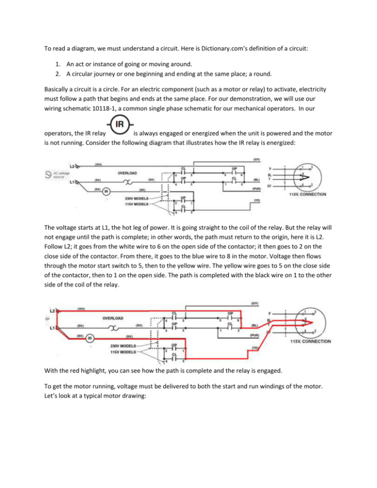
To read a diagram, we must understand a circuit. Here is Dictionary.com’s definition of a circuit: 1. An act or instance of going or moving around. 2. A circular journey or one beginning and ending at the same place; a round. Basically a circuit is a circle. For an electric component (such as a motor or relay) to activate, electricity must follow a path that begins and ends at the same place. For our demonstration, we will use our wiring schematic 10118-1, a common single phase schematic for our mechanical operators. In our operators, the IR relay is always engaged or energized when the unit is powered and the motor is not running. Consider the following diagram that illustrates how the IR relay is energized: The voltage starts at L1, the hot leg of power. It is going straight to the coil of the relay. But the relay will not engage until the path is complete; in other words, the path must return to the origin, here it is L2. Follow L2; it goes from the white wire to 6 on the open side of the contactor; it then goes to 2 on the close side of the contactor. From there, it goes to the blue wire to 8 in the motor. Voltage then flows through the motor start switch to 5, then to the yellow wire. The yellow wire goes to 5 on the close side of the contactor, then to 1 on the open side. The path is completed with the black wire on 1 to the other side of the coil of the relay. With the red highlight, you can see how the path is complete and the relay is engaged. To get the motor running, voltage must be delivered to both the start and run windings of the motor. Let’s look at a typical motor drawing: The numbers correspond with wires in the motor. The lines going to them from outside the circle are wires coming from the control box, or going to the brake. The start windings are numbers 8 and 5. The diagram should show a connection between the two as they are connected by a motor centrifugal start switch. When the motor gets up to speed, the start switch opens up, cutting off the start windings and power to the IR relay (more on that later). The run windings have two sets for each direction, 1 and 3 for one way, 2 and 4 for the other direction. OL is a thermal overload in the motor, if it gets too hot, the overload opens (more on that later). To energize the motor, the circuit must be completed from L1 to the motor to L2. As you can see from the schematic, the normally open (NO) contacts on the contactor prevent that voltage from flowing: If the contactor is activated, those contacts close. Here, the open side is active: This allows voltage to flow to the start windings of the motor: And also to the run windings: So what activates the contactor to run the motor? This would be the control circuit. First of all, we do not want the controls the customer will use and the technician will install to be using high voltage. For safety, we transform the 120vac (or higher) to 24vac. This is done with the transformer. Here is how the transformer gets power. Once again, you will notice that the transformer will only supply 24vac if the high voltage going to it completes its circuit. You will also see that the one leg of power for the transformer runs through the motor overload. When the motor overheats, the overload opens, cutting off power to the transformer. The coil part of the contactor energizes with 24vac. To activate the contactor, the control 24vac coming from the transformer has to complete its circuit. This is done by pressing the open button. You should notice that the IR relay contact is NO, but the schematic shows the circuit with no power. When the operator has power, the IR is engaged and the contact is closed. When the open button is pressed, the control voltage from the transformer can complete its circuit and activate the contactor. The open button completes the circuit but it does not have to be held for the unit to keep going open. Also remember that when the start switch in the motor drops out or opens, the IR relay looses power. What keeps the unit running open is a “latching circuit.” This is done using the 13 and 14 NO contacts on the contactor. It ‘latches’ the contactor to keep it engaged. When the coil is energized, the NO contacts close to form an alternate path for the circuit to be maintained. Now, in this latched state, the unit would keep running, so we need something to stop it. That is the job of the open limit switch. The limit is wired NC so when the switch is activated, it opens up, breaking the circuit. Here is the close button activating the close contactor. Notice that the latching circuit for the close side is not in place. Our mechanical operators are shipped in C2 mode, where the close button has to be held for the unit to keep running close. Moving the red wire from terminal 2 to terminal 3 will allow the latching circuit to work (B2 mode). Here are the circuits in C2 and B2 modes: C2: B2: We have seen the function of the open and close contactors; let’s move on to the relays, R1 and IR. Te R1 relay provides for open override, where an open command will override a close command. Since the IR relay is powered through the start switch in the motor, this makes the motor have to come to a full stop before the operator can go the opposite direction. Here is how the two work together to reverse a door. Say the door is closing in B2 mode: Then, the safety edge is activated: Notice that the edge wires through the auxiliary close limit switch to terminal 1, so it is an open command. However, the IR relay is open so the open side of the contactor cannot be activated. You do not want both sides of the contactor actived at the same time. Instead, the R1 relay gets activated. The two contacts on the R1 relay provide a constant open command and cuts off the close circuit. As you can see, the R1 relay has its own latch circuit to keep it engaged and to provide a continuous open command. The R1 relay cuts off the close circuit, so when the motor stops and the IR relay reengages; the open contactor will activate and send the door open.
