LUKUGA BARRAGE DRAFT design report-30-09-2013
advertisement
DESIGN AND SUPERVISION
OF
WORKS
FOR
THE CONSTRUCTION
OF
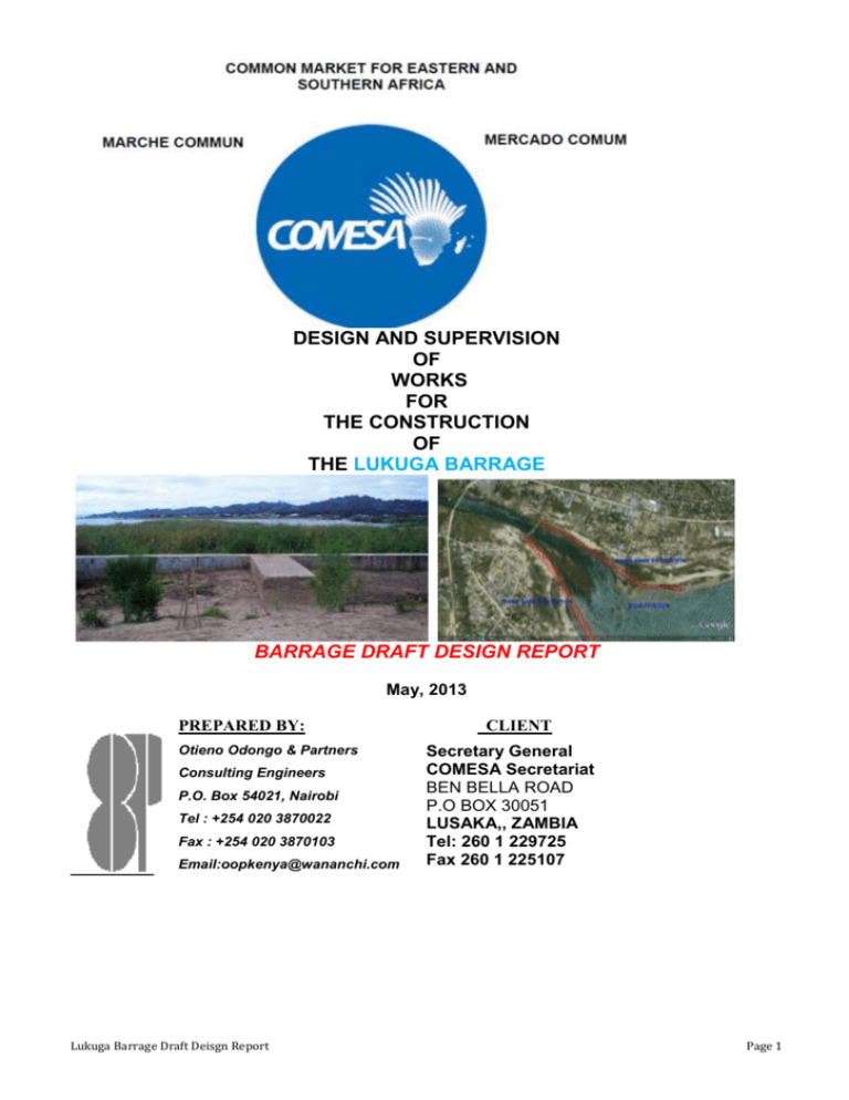
THE LUKUGA BARRAGE
BARRAGE DRAFT DESIGN REPORT
May, 2013
PREPARED BY:
Otieno Odongo & Partners
Consulting Engineers
P.O. Box 54021, Nairobi
Tel : +254 020 3870022
Fax : +254 020 3870103
Email:oopkenya@wananchi.com
Lukuga Barrage Draft Deisgn Report
CLIENT
Secretary General
COMESA Secretariat
BEN BELLA ROAD
P.O BOX 30051
LUSAKA,, ZAMBIA
Tel: 260 1 229725
Fax 260 1 225107
Page 1
TABLE OF CONTENTS
ABBREVIATIONS ........................................................................................................................................... 4
Chapter 1 EXECUTIVE SUMMARY ................................................................................................................ 5
1.1
Objective ............................................................................................................................................ 5
1.2
Recommended Layout ........................................................................................................................ 5
1.3
Cost estimate ...................................................................................................................................... 6
Chapter 2 INTRODUCTION AND DAM SITING ........................................................................................... 7
Introduction ....................................................................................................................................................... 7
2.1
Purpose and objective ........................................................................................................................ 7
2.2
Background information .................................................................................................................... 7
2.3
Hydrology .......................................................................................................................................... 8
2.4
Site investigations and field work ...................................................................................................... 8
Geotechnical Conditions at site ........................................................................................................................ 9
2.5
Figure 1: geophysical survey point, old barrage location ................................................................. 9
2.6
Figure2: curves of interpreted VES, old barrage location .............................................................. 10
2.7
Table 1: geophysical survey data analysis, old barrage location .................................................... 11
2.8
Figure 3: geophysical survey point, ................................................................................................. 12
2.9
Figure4: curves of interpreted VES, away from old barrage location ............................................. 13
2.10
Table 2: geophysical survey data analysis, away from old barrage location .................................. 14
Grouting procedures ....................................................................................................................................... 15
2.11
Introduction ..................................................................................................................................... 15
2.12
Site location and topography ........................................................................................................... 16
Chapter 3 BARRAGE SELECTION AND DESIGN CRITERIA ................................................................. 19
3.1
General ............................................................................................................................................ 19
3.2
Barrage type selection ..................................................................................................................... 19
3.3
Classification as per function and use ............................................................................................. 19
3.4
Classification as per hydraulic design ............................................................................................. 20
3.5
Classification as per material use .................................................................................................... 20
Barrage design criteria.................................................................................................................................... 21
3.6
Seismic Dyke .................................................................................................................................... 21
3.7
Zoned rockfill Dam .......................................................................................................................... 22
3.8
Blanketed rock fill dam .................................................................................................................... 22
3.9
Precast concrete caisson .................................................................................................................. 23
3.10
Concrete Gravity weir with central overflow spillway .................................................................... 23
3.11
PROPOSED BARRAGE ................................................................................................................... 24
3.12
Bridge .............................................................................................................................................. 24
Hydraulic design .............................................................................................................................................. 25
3.13
Design against overtopping-Freeboard ........................................................................................... 25
3.14
Wave height...................................................................................................................................... 26
3.15
Spillway Design ............................................................................................................................... 28
3.16
Stilling basin and energy dissipaters ............................................................................................... 30
3.17
Design input data ............................................................................................................................. 30
3.18
Stilling basin and energy dissipaters ............................................................................................... 31
3.19
Sluice gate sizing.............................................................................................................................. 33
3.20
Mechanical Facilities Design .......................................................................................................... 34
3.21
Fish Ladder and Fish ways .............................................................................................................. 35
BRIDGE DESIGN ........................................................................................................................................... 36
3.22
Selection of bridge type. ................................................................................................................... 36
3.23
Geotechnical Investigation .............................................................................................................. 39
3.24
Bridge Superstructure design........................................................................................................... 39
3.25
Bridge Substructure design .............................................................................................................. 40
Chapter 4 STRUCTURAL SYSTEM AND MATERIALS ............................................................................ 42
4.1
Structural system .............................................................................................................................. 43
4.2
Loadings........................................................................................................................................... 43
4.3
Foundations ..................................................................................................................................... 43
4.4
Column piers .................................................................................................................................... 43
4.5
Walls ................................................................................................................................................ 43
4.6
Fire resistance ................................................................................................................................. 43
4.7
Concrete ........................................................................................................................................... 43
4.8
Reinforcement bars .......................................................................................................................... 43
Lukuga Barrage Draft Deisgn Report
Page 2
4.9
Welding consumables....................................................................................................................... 44
4.10
Foundation Condition and Seismic loading Considerations ........................................................... 44
Chapter 5 STRUCTURAL DESIGN CALCULATIONS ............................................................................... 45
BARRAGE ....................................................................................................................................................... 45
Forces acting on the Barrage .......................................................................................................................... 45
5.1
Figure 7: Diagram showing forces acting on the barrage .............................................................. 45
Load Combinations for Barrage .................................................................................................................... 48
ACCESS ROAD AND BRIDGE .................................................................................................................... 49
Forces acting on the Bridge ............................................................................................................................ 49
5.2
Characteristic Loads ........................................................................................................................ 49
Live Loads ..................................................................................................................................................... 49
Chapter 6 REFERENCES ................................................................................................................................. 50
Chapter 7 annex ................................................................................................................................................. 51
Lukuga Barrage Draft Deisgn Report
Page 3
ABBREVIATIONS
A
Flow area
a.m.s.l
above sea level
a.m.s.l
above mean sea level
BS
British Standard
C
drowned weir formula Constant
DRC
Democratic Republic of Congo
Fcu
concrete strength grade
Fr
Froude Number
fy
Yield strength
L
length
M
metres
OO&P
Otieno Odongo & Partners consulting engineers
q
Flow rate m3/s
Q
Volume of Discharge, m3
S
channel slope
USBR
United State Bereu of Reclamation
V
Velocity, m/s
VES
Vertical Electric Sounding
Lukuga Barrage Draft Deisgn Report
Page 4
CHAPTER 1 EXECUTIVE SUMMARY
The COMESA Secretariat commissioned M/s Otieno Odongo & Partners Consulting Engineers, to
undertake the Engineering design and supervision of the reconstruction of the Lukuga Barage on
Lake Tanganyika.
The Lukuga River originates from Lake Tanganyika and flows into the Congo River, which is the
only outlet for the water flow of Lake Tanganyika.
1.1 Objective
The overall objective of the report is finalize the general layout of the Lukuga barrage project:
selection of the type of barrage, localization and sizing of the spillway, localization and sizing of
stilling basin and sluices, and access bridge.
1.2 Recommended Layout
The finally recommended layout is:
Concrete Gravity dam
Crest elevation; 778m
Normal retention level; 774m
Height above river bed varies with a minimum of 5 m and maximum of 8m.
Type: The planned barrage structure will be a concrete gravity ogee with central overflow
spillway, with sluices to manage silt deposition and also when fitted with gates to allow
discharge of flood flow when in open position and retain water discharge during low flow.
Spillway
Spillway design flood: 5000 years return period.
It is an overflow weir at the centre of the barrage with a crest length of 180m, stilling basin
and energy dissipators.
Bridge
The bridge is 480m long with a two lane deck with column piers at 20m centres. It is
founded at the same level with barrage and friction piles incorporated on the column bases.
The soffit of the beams rest at the crest elevation of 778m a.s.l.
Lukuga Barrage Draft Deisgn Report
Page 5
1.3 Cost estimate
Below is a summary extracted from the detailed bill of quantities.
SUMMARY OF THE BILLS OF QUANTITIES
Bill
No.
Description
Amount
($USD.)
1,763,826.04
1
PRELIMINARIES AND GENERAL
2
SETTING OUT
3
SITE CLEARANCE AND TOP SOIL
STRIPPING
4
RIVER PROTECTION EARTHWORKS
3,138,962.21
5
EXCAVATION AND FILLING FOR
STRUCTURES
2,288,744.30
6
CONCRETE WORKS
7
ROAD FURNITURE
8
GROUTING
499,808.75
9
SITE INVESTIGATION
121,715.00
10
ROADS AND PARKING
378,083.47
11
Dayworks
151,406.25
SUB - TOTAL
Contingency = 10%
22,844.09
670,661.00
43,340,288.57
6,312.50
52,382,652.18
523,826.52
Variation of Prices 6.5%
3,404,872.39
16% VAT
8,381,224.35
TOTAL PROJECT SUM FOR THE WORKS
Lukuga Barrage Draft Deisgn Report
64,692,575.44
Page 6
CHAPTER 2 INTRODUCTION AND DAM SITING
Introduction
Lake Tanganyika is situated within the western Great Rift Valley and is confined by mountainious
walls of the rift valley.
The main ports on the lake are kalemie railhead to DRC rail network, Kigoma railhead to Dar es
Salam in Tanzania, Mupulungu railhead for Zambia and Bujumbura port.
2.1 Purpose and objective
The purpose of the Dam/ Barrage studies is to provide a control structure at source of river Lukuga
that will maintain the predetermined water level.
The objective of this study is aimed at preparing a design for the appropriate water control structure
at the beginning of river Lukuga that will regulate and stabilize the lake water levels to desired
levels which will enable the ports to operate at all times.
2.2 Background information
The Lukuga River is the main outlet of water from Lake Tanganyika. It is located on the western
part of the lake with its source at Kalemie in Katanga Region. It flows into River Congo eventually
entering Pacific Ocean.
Lake Tanganyika has catchment area that is riparian to Republic of Tanzania, Republic of Burundi,
Republic of Zambia and Democratic Republic of Congo.
The major rivers from the above catchments feeding into the lake includes; River Ruzizi from Lake
Kivu, River Malagarasi from Tanzania, and River Kalambo from Malawi.
The Lake Tanganyika has a number of ports including kigoma, kalemi, uvira, etc serving the
riparian countries, and the flacuation of the lake levels often adversely affects the operations of
these ports. In order to reduce the adverse impacts of the flacuations of the lake levels it is necessary
that water balance thereon be maintained such that levels fluctuations is limited to a predetermined
minimum that will allow use of the ports at all times. The purpose of the Dam/ barrage studies is to
provide a control structure at mouth of river lukuga that will maintaion the predetermined water
level.
The design looks into geotechnical studies at the proposed control structure location, metrology and
hydrology of the catchment area and lake water balance and levels fluctuations, design of the
control structure options.
Lukuga Barrage Draft Deisgn Report
Page 7
2.3 Hydrology
From hydrological report, the required level for Kalemie port for optimal operations of port
shipping was found to be 774.0m a.m.s.l. and the proposed height of the dam above the current
water level of 770m a.m.s.l (from 2011 field study) is 4m. The location of the barrage from the
river source is approximately 1.12km, where the distance to contour 774 is relatively small and up
stream of the railway bridge.
2.4 Site investigations and field work
Extensive geophysical survey was undertaken during February 2011 along Lukuga River with the
main objective of determining the underground lithology within and along the 1200m long stretch
of the river. The geophysical survey carried out 11 No. deep lithology and plotted the river
underground soil and rock conditions. From the review of the 11 number lithology plots two sites
were selected across the river as potential locations of the proposed dam design options. These are
the locations where the firm hard ground is at shallowest depth.
The existing barrier which was constructed in the year 1952 was damaged and vandalized, rendering
it ineffective in controlling the flow.
Lukuga Barrage Draft Deisgn Report
Page 8
Geotechnical Conditions at site
Location A:
Construction of barrage at the previuosly constructed site through the following locations
2.5 Figure 1: geophysical survey point, old barrage location
Lukuga Barrage Draft Deisgn Report
Page 9
VES 14 – 35M 0743292; UTM 9345930, on HEP 04
VES 03 – 35M 0743209; UTM 9345838, on HEP 01
VES 04 – 35M 0743090; UTM 9345554, on HEP 02
VES 09 – 35M 0743073; UTM 9345412, on HEP 03
The curves of the interpreted Vertical Electrical soundings are as follows:
2.6 Figure2: curves of interpreted VES, old barrage location
Lukuga Barrage Draft Deisgn Report
Page 10
Curve No. VES 09
LUKUGA RIVER KALEMIE DRC
SOUTH OF LUKUGA RIVER
Curve No. VES 04
LUKUGA RIVER KALEMIE, DRC,
SOUTH OF LUKUGA RIVER
Curve No. VES 04
LUKUGA RIVER KALEMIE DRC,
NORTH OF RIVER AT THE EXISTING
BARRAGE
Curve No. VES 14
LUKUGA RIVER KALEMIE DRC,
NORTH OF LUKUGA RIVER AT THE
EXISTING BARRAGE 124m NE OF VES
03
Formation
Thickness (m)
True
Resistivity
(ohm m)
Expected
Geological
Formation
0 – 0.92
517
Sands deposits
0.92 – 3.80
57
Sandstone
3.80 – 10.07
14
Gravels
10.07 – 18.20
56
Gravels
Over 18.20
6
Clayey soil
0 – 0.37
1934
Sands deposits
0.37 – 1.59
184
Sandstone
1.59 – 15.17
26
Gravels
15.17 – 36.84
9
Clayey soil
Over 36.84
20
Gravels
0 – 0.77
1577
Sands deposits
0.77 – 2.87
130
Sandstone
2.87 – 17.40
27
Gravels
17.40 – 45.25
9
Clayey soil
45.25 – 56.77
26569
Quartzite Sill
Over 56.77
30
Gravels
0 – 0.53
862
Sands deposits
0.53 – 2.30
80
Sandstone
2.30 – 3.26
8
Clay soil
3.26 – 38.17
16
Gravels
Over 38.17
20
Gravels
2.7 Table 1: geophysical survey data analysis, old barrage location
Lukuga Barrage Draft Deisgn Report
Page 11
Location No B:
CONSTRUCTION OF WEIR/BARRAGE DOWNSTREAM OF THE EXISTING
BARRAGE FOUNDATION REMNANTS SITE THROUGH THE FOLLOWING
LOCATIONS
2.8 Figure 3: geophysical survey point,
Lukuga Barrage Draft Deisgn Report
Page 12
VES 14 – 35M 0743292; UTM 9345930, on HEP 04
VES 01 – 35M 0743209; UTM 9345838, on HEP 01
VES 05 – 35M 0743063; UTM 9345658, on HEP 02
VES 09 – 35M 0743073; UTM 9345412, on HEP 03 at 90m downstream
When plotted on Topographic Map forms a straight line with distance across the river being
approximately 256m.
The curves of the interpreted Vertical Electrical soundings are as follows:
2.9 Figure4: curves of interpreted VES, away from old barrage location
Lukuga Barrage Draft Deisgn Report
Page 13
Formation
Thickness (m)
True Resistivity
(ohm m)
Expected Geological
Formation
0 – 0.92
517
Sands deposits
0.92 – 3.80
57
Sandstone
3.80 – 10.07
14
Gravels
10.07 – 18.20
56
Gravels
Over 18.20
6
Clayey soil
Curve No. VES 05:
0 – 0.37
4360
Sands deposits
LUKUGA RIVER
KALEMIE, DRC SOUTH
OF LUKUGA RIVER
0.37 – 1.59
321
Sandstone
1.59 – 8.24
30
Gravels
8.24 – 31.95
9
Clayey soil
Over 31.95
20
Gravels
0 – 0.37
2320
Sands deposits
0.37 – 1.59
136
Sandstone
1.59 – 7.02
19
Gravels
7.02 – 44.52
9
Clayey soil
44.52 – 48.90
146
Sandstone
Over 48.90
20
Gravels
0 – 0.53
862
Sands deposits
0.53 – 2.30
80
Sandstone
2.30 – 3.26
8
Clay soil
3.26 – 38.17
16
Gravels
Over 38.17
20
Gravels
Curve No. VES 09:
LUKUGA RIVER
KALEMIE DRC SOUTH
OF LUKUGA RIVER
Curve No. VES 1
LUKUGA RIVER
KALEMIE, DRC, NORTH
OF RIVER 70m
downstream of existing
barrage
Curve No. VES 14
LUKUGA RIVER
KALEMIE DRC, NORTH
OF LUKUGA RIVER AT
THE EXISTING
BARRAGE 124m NE OF
VES 03
2.10
Table 2: geophysical survey data analysis, away from old barrage location
Lukuga Barrage Draft Deisgn Report
Page 14
OBSERVATION: one of the findings of the geophysical survey was the determination of the
apex of the lukuga river sill which is consistent with positions marked option site A and B, the
ground conditions became better as you move away from the lake.
From the measurements interpretation (given in table above) the underground foundation strata
is determined to be that of sandstone is found at depths varying from 1m to 3m, as the first layer
of rock lying above gravel. Gravel extends to lengths not less than 17m.
With reference to BS 8004:1986, table 1, a bearing pressure of 450kn/m2 has been adopted for
the design.
The required foundation treatment consists of cleaning the top sands deposit and part of the top
mudstone up to depth of 3m from original bed level.
Below the excavation curtain and contact grouting to 10m and 6m respectively is applied to
close the area from leakage/seepage.
Grouting procedures
2.11
Introduction
All holes for grouting, shall be drilled at the locations, in the direction, angle, and to the depths
indicated or as directed by the Engineer. A maximum tolerance for deviation in angle and direction
shall be (30) the first series of holes to be drilled and grouted shall be at (5) - foot intervals and
hereinafter are referred to as primary holes. The location of secondary and succeeding series
(intermediate) holes shall be determined by the split spacing method as defined in paragraph SPLIT
SPACING. The number of grout holes shall be increased, progressively, by the split spacing method
as defined in paragraph SPLIT SPACING. The number grout holes shall be increased progressively,
by the split spacing method as deemed necessary by the Engineer until the amount of grout used indicates that the foundation is tight. Each hole drilled shall be protected from becoming clogged orobstructed by means of a cap or other suitable device on the collar and any hole that becomes
clogged or obstructed due to fault of the contractor before completion of operations shall be cleaned
out in a manner satisfactory to the Engineer or another hole provided by and at the expense of the
Contractor.
Records:
The Engineer will keep records of all grouting operations, such as a log of the grout holes, results of
washing and pressure testing operations, time of each change of grouting operation, pressure, rate of
Lukuga Barrage Draft Deisgn Report
Page 15
pumping, amount of cement for each change in water/cement ratio, and other data deemed by him to
be necessary. The Contractor shall furnish all necessary assistance and cooperation to this end.
2.12
Site location and topography
Location of the dam/dyke is within the mouth of the lukuga river for effective control of the
flooding impacts of the river ponding area upstream of the dam and erosion of the sandy river
banks.
The Lake Tanganyika lies between Lat 30 20’ to 8048’ S and Long 2905’ to 31015’. OO&P carried
out topographical survey of the river lukuga mouth and a topo plan produced. The topo plan covered
a stretch of 2km of the river from the source, with 1m contour intervals. The remains of the
damaged barrier were also captured.
The site is generally gentle with elevations varying from 766m a.m.s.l to 774m a.m.s.l.
This Topography allows fitting of a weir of crest height of 5m from riverbed to raise water level to
774m to as proposed on the hydrological study.
From site topography and the required crest elevation of 774m, the following Weir parameters were
noted,
The crest height from river bed is
774 -769 = 5m.
The weir height above river bank is 774 –774 =0m.
Lukuga Barrage Draft Deisgn Report
Page 16
Figure 5: barrage location at Kalemie
Lukuga Barrage Draft Deisgn Report
Page 17
Figure 6: barrage location at Kalemie (topography)
Lukuga Barrage Draft Deisgn Report
Page 18
CHAPTER 3 BARRAGE SELECTION AND DESIGN CRITERIA
3.1 General
Barrage structure is designed to facilitate the control of water flow to river lukuga, to raise the head
of the lake by 4m within Kalemie Port (as per the hydrological report). The water level required for
port is 774m a.m.s.l. a bridge will be running above the barrage for vehicular transport.
Considering the foundation condition where depth of firm materials range from 1 to 3 metres along
the proposed barrage alignment above the lukuga river, the foundation of the weir is proposed to be
at elevation 769-3=766m, (769 is the river bed level) the overall height of the weir is 774-766=8m
on the overflow potion.
3.2 Barrage type selection
The geological conditions on site and geometry of valley dictate that a rigid gravity dam are
considered practical. The selection of the dam type options are as follows:
LUKUGA
BARRAGE
USE
HYDRAULIC
DESIGN
MATERIALS
USED
HEIGHT
STORAGE
OVERFLOW
CONCRETE
LARGE
DIVERSION
NON
OVERFLOW
MASONRY
MEDIUM
EARTHFILL
SMALL
DETENTION
ROCKFILL
3.3 Classification as per function and use
Storage Barrage
This is the most common type of barrage normally constructed to store excess flood water which
can be utilized later when demand exceeds the flow in river. The Storage dams may be constructed
for various purposes such as irrigation, water supply, hydro-power generation etc. they may be
made of concrete, stone or earth or rock fill etc.
Lukuga Barrage Draft Deisgn Report
Page 19
Detention barrage
These types of barrage are mainly constructed to control flood. This type of barrage stores water
temporarily and releases it gradually at a safe rate when the flood recedes. Detention barrage
provides safeguard against possible damage due to flood on the downstream side of it. Sometimes a
detention dam may also be used as storage dam.
Diversion Barrage
The purpose of diversion dam is necessarily different. It is constructed to divert the river water into
canal, conduit etc. For this purpose, mostly a weir or low level dam is constructed across the river to
raise the water level which can be diverted as per the needs. This type of dam may be used for water
supply, irrigation or some other purposes.
3.4 Classification as per hydraulic design
Overflow Barrage/Dam:
An overflow dam is built to allow the overflow of surplus discharge above the top of it. They are
generally built of masonry or concrete and they are gravity type of dam. Usually dams are not
designed as overflow for their entire length. Only few meters of its length is kept as overflow
section
Non-Overflow Barrage/Dam:
In this type of dam, water is not allowed to overtop the dam. The top of the dam is fixed at a higher
elevation than the expected maximum flood level. Since water is not allowed to overtop, it can be
constructed of large variety of materials such as earth, rock fill, masonry, concrete etc.
3.5 Classification as per material use
The dam type options considered are:
Embankment dam which includes;
Seismic dyke
Earth dam
Rock fill dam
Zoned rock fill dam
Concrete dams which include;
Precast concrete caisson
Gravity concrete weir
Lukuga Barrage Draft Deisgn Report
Page 20
Barrage design criteria
These dam/dyke options design concepts have been elaborated on in order to determine their
technical viability.
3.6 Seismic Dyke
This option consists of an embankment constructed in dry and compacted materials in embankment
designed to resist earthquake loading. The embankment is zoned and consists of sand and gravel
shoulder fills separated with silt/clay core and filter.
The area where the embankment is constructed is dewatered dry using constructed upstream and
downstream parallel sets of temporary cofferdams. The embankment is built in sections to allow
reusing the cofferdam materials.
Considering the foundation soils consisting of sandstones and gravel materials the embankment
design considered in this option has the following particulars:a) Slope inclinations of 5:1(horizontal: vertical) on the upstream slope and 7:1 on the
downstream slope.
b) The crest of the dam would be 10m wide ( to allow for 2way traffic) and provide for 2.5m
of freeboard above mean lake level.
c) An overexcavation depth of 3m is provided under the embankment crest, and an
overexcavation depth of 5m is provided under embankment toes. An additional
embankment volume computed on basis of average settlement of 6% of the unexcavated
soft soils over the entire width of the embankment.
The main advantage of this option is that the dry construction method allows compaction of the
embankment materials that makes it stable.
The disadvantages:
Extensive cofferdams are required for temporary dewatering and staging of construction is
complex.
Expensive river diversion works required.
The location does not have suitable material for construction of impermeable core.
A large river diversion channel required
Require a side spillway
Lukuga Barrage Draft Deisgn Report
Page 21
All the disadvantages combined makes the option time consuming and expensive to construct.
3.7 Zoned rockfill Dam
This option consists of an embankment built with rockfills in its outer shells and soil core. This is
constructed in the wet, and this do not allow for compaction of the embankment materials. Rock is
preferred, as compacted rockfills do not have substantial strength losses during earthquake,
compared to uncompacted soil fills.
As for seismic dyke, 3 to 5m loose foundation soils will be excavated and replaced with
embankment material. An additional embankment volume computed on basis of average settlement
of 6% of the unexcavated soft soils over the entire width of the embankment.
Slope inclinations of 5:1(horizontal: vertical) on the upstream slope and 7:1 on the downstream
slope.
The crest of the dam would be 20m wide (to allow for construction of the multiple lift rock dykes)
and provide for 2.5m of freeboard above mean lake level.
Large volumes of rocks, makes it expensive and time comsuming. They require a separate spillway
away from the main dam.They require heavy maintenance cost and constant supervision.They are
more susceptible to be damaged by floods than any other type of dam.
3.8 Blanketed rock fill dam
This is an option that consists of an embankment built in wet and entirely out of rockfills. To
mitigate seepage through the dam, ablanket would need to be placed on the upstream slope.
Conventionally, this is usually an asphalt or concrete pavement. However, construction below sea
level precludes those for this option. The upstream blanket will therefore consist of depositing fine
grained soils on the upstream slope to plug the rock fill.
Alternately, bentonite slurry would be constructed through the dam along its crest to provide a
seepage barier. As for seismic dyke, 3 to 5m loose foundation soils will be excavated and replaced
with embankment material. An additional embankment volume computed on basis of average
settlement of 6% of the unexcavated soft soils over the entire width of the embankment.
Slope inclinations of 5:1(horizontal: vertical) on the upstream slope and 7:1 on the downstream
slope.
The crest of the dam would be 10m wide and provide for 2.5m of freeboard above mean lake level.
Lukuga Barrage Draft Deisgn Report
Page 22
Blanket rockfill dam is prone to high permeability hence large seepage quantities are expected. This
option also requires a separate spillwayaway from the main dam.
3.9 Precast concrete caisson
This option utilizes large precast concrete circular caisons to form a dam structure. The concrete
will provide for non corrosive structure, the caisons would be cast onshore and floated into position.
The caisson would be sunk by excavating the soils within and immediately below the caisson. The
remainder of the caisson would be filled with soil. The stability analysis requires that 22m in
diameter and 25m high caisson is required; the width height ratio is kept the same for lower sea
levels. The individual caisons will be tied together using steel sheet pile arcs, and the area between
the arcs filled with lean concrete.
Advantage of this option is that no over excavation of foundation soils would be required. However,
the concept is unique for application as a dam, and the rigidity of the system would not be as
accomodatind (as embankments) to seismic deformations.
3.10
Concrete Gravity weir with central overflow spillway
This option consist of Construction of a concrete gravity overflow weir with central overflow
spillway supported on reinforced concrete base on firm underground formation. Below the concrete
weir a curtain grouting layer is constructed to reduce water loss through seepage.
Advantages:
It is Stronger and more stable than any other type of dam
It can house an overflow spillway to pass excess flood water safely.
It can be built of any height provided suitable foundation is available to bear all the loads coming on
it.
The failure of a gravity dam is not sudden at all. It gives sufficient time for evacuation of area
downstream of it.
Though its Initial cost is higher, and It needs skilled labor and mechanized plants for construction
and It may take more time in construction, its is the most prefered option for Lukuga.
From considerations of technical viability of construction of the above options it was considered
that the concrete gravity dam with central overflow spillway was the suitable dam type for Lukuga
Dam/Dyke. The design therefore adopted this type for futher hydraulic and structural design
analysis.
Lukuga Barrage Draft Deisgn Report
Page 23
3.11
PROPOSED BARRAGE
The planned barrage structure will be a concrete gravity ogee with central overflow spillway, with
sluices to manage silt deposition and also when fitted with gates to allow discharge of flood flow
when in open position and retain water discharge during low flow.
The proposed barrage structure is 5m high above the river bed at deepest point and has a crest weir
length of 180m, a non overflow concrete wall of 166 m and 134m on either sides of the 180m
overflow weir and an 480m access concrete bridge deck to allow access to the sluices penstock
gates for the control of sluices gates penstocks facilities and also vehicles connecting the north and
south sides of Kalemie Port.
3.12
Bridge
The bridge is to connect the two towns to the port.
The bridge is a modular bridge 480m long composing of 24No. 20m span centre to centre bearings.
7.0m carriageway with 2 No. 1.9m clear walkways, 50mm thick surfacing.
The beams grillage is composed of 5 No. 1500 deep by 500mm wide main beams simply supported
on free bearings, 2No. 1500mm deep by 300mm wide Diagphrams each on support. The height of
the freeboard is 4m above the barrage crest overflow width.
Lukuga Barrage Draft Deisgn Report
Page 24
Hydraulic design
3.13
Design against overtopping-Freeboard
Overtopping waves can constitute a danger to the barrage when they exert lateral loads on the
retaining gravity wall. Wave overtopping must therefore be prevented by giving the dam sufficient
freeboard above the maximum design water level. Freeboard is the vertical distance between the
maximum reservoir water level and the crest of the dam without camber. Free board (Ho) is the sum
of the significant wave height (Hw), wave run-up (Rw) and wind set-up S computed using the
following empirical relationships (based on UK Reservoir Flood Standards).
Rw
Hw
Hw
0 .4
L
0 .5
Cot
Zuiderzee formula:
S
U 2F
1400 * D
L 5.12 * T 2
Where:
Hw is significant wave height (m),
Rw is wave run-up (m)
S is wind set-up (m)
U is the wind velocity over water (km/hr)
F is reservoir fetch (km)
L is wave length (m)
D is average water depth along the central radial (m)
F is reservoir fetch (m)
Ho is the freeboard (m)
is the angle of upstream face of the dam with horizontal
T is the wave period (sec)
Lukuga Barrage Draft Deisgn Report
Page 25
3.14
Wave height
Waves are generated on the surface of the reservoir by the blowing winds, which exert a pressure on
the downstream side. Wave pressure depends upon wave height which is given by the equation
Molitor's empirical Formula
For F < 32 km, and
for F > 32 km
Where
is the height of water from the top of crest to bottom of trough in meters.
V – Wind velocity in km/hour
F – Fetch or straight length of water expanse in km.
Wind velocity overland is 110km/h associated over water is 1.15 times larger; giving 126.5 km/hr
for design wind speed.
variables
velocity
normal pool
max reservoir
Fetch
norm. pool =
max reservoir =
(VF)^0.5
F^0.25
norm. pool =
max reservoir =
127 km/hr
92 km/hr
2.64 km
0.58478632 m
0.498707449 m
0.032(FV)^0.5
0.032(FV)^0.5
18.2745725
1.274679442
1.10258301 m
1.007896252 m
9% of waves may exceed the significant wave height hence the corresponding design wave height
is;
1.1x1.002348=1.1026m.
Lukuga Barrage Draft Deisgn Report
Page 26
Wave run-up Rw (m) and wind set-up, S (m)
Hw
F
D
U
1.10
2.64
1400
90
127
m
km
m
km/hr
S is wind set-up (m)
Tm
S= 0.021554051 m
Tp=0.07118*F^0.3*U^0.4
F
2640 m
U 35.13888889 m/s
g
10 m/s
T= 3.141625198 s
2.576132662
L is wave length (m)
= 33.97867261 m
Rw is wave run-up (m)
Hw/L=
Tan
Cot
0.032449267
572.957213
0.001745331
Rw=
2.75 m
Total Freeboard= Rw+Hw+S
3.88 m
The freeboard adopted therefore is 4.0 m.
Lukuga Barrage Draft Deisgn Report
Page 27
3.15
Spillway Design
Spillways are hydraulic structures designed to release excess water from a reservoir to a stretch
downstream of the dam. This protects the dam from destruction from debris, wave action, and
floods. A spillway is sized to provide the required capacity, usually the entire design flood, at a
specific reservoir elevation. The spillway shall be designed as open earth channel broad crested
weir. Spillway capacity (Q) and Dimensions
Q
2
2
h * b gh
3
3
Q
b
1.7 * h
3
2
Where;
b is the spillway width (m)
h is the design upstream water head above the spillway crest,
Q is the design flood
a. Spillway design flood
The proposed return period has been checked from Q1000 and Q5000. The maximum Q is used for
weir sizing. This flood is to be passed by the spillway after routing through the reservoir with full
freeboard allowance on the barrage meaning that with a 127km/hr wind the waves so produced will
not overtop the crest of the barrage.
Lukuga Barrage Draft Deisgn Report
Page 28
b. Probable Maximum Flood (PMF)
This flood is to be passed by the spillway after routing through the reservoir with a nominal 0.50m
freeboard on the barrage and the waves produced by 127km/hr wind may be allowed to run on the
wave wall provided on the crest.
PMF METHOD
ln(PMF+1)=1.175*(ln(CA+1))^0.755+3.133
where PMF, Probable Maximum Flood,
m3/s
CA, Catchment Area (km2)
CA
>32 take
200km2
=
7.27367
PMF
1440.83 m3/s
design floods are calculated has a proportion
of the PMF, i.e. Q5000=0.46*PMF and
Q1000=0.38*PMF
Q1000
Q5000
PMF
547.516 m3/s
662.782 m3/s
1440.83 m3/s
c. Spillway width
Q
2
2
h * b gh
3
3
Q= 1440.83 m³/s
h=
h^(3/2)=
4 m
freeboard
max
8
b 105.943 m
Since the current width of the channel at the proposed site is 180m, a spillway width of 180 m will
be adopted.
Lukuga Barrage Draft Deisgn Report
Page 29
3.16
Stilling basin and energy dissipaters
Hydraulic design is of 5m high concrete gravity overflow weir above the river bed supported on
reinforced concrete base founded at the firm ground which is 3m below the river bed level. The
overall height of the barrage from foundation is 8m.
3.17
Design input data
river bed elevation
planned weir crest level
upstream face slope
downstream face slope
design discharge
length of the weir
769 m
774 m
vertical
0.75:1
600 m3/s
180 m
hydraulic analysis to
determine design head
discharge Q=CxLxH^2/3
where, Q=600m3/s, L=180m,
Cd=2.2
design head,
H=(Q/(2.2X180))^2/3
1.31918 m
height crest above riverbed
P
P/Hd=P/He=5/1.32
(Hd+P)/He=(1.32+5)/1.32
> 1.7 Therefore Cd is not
affected by downstream apron
and tailwater
Lukuga Barrage Draft Deisgn Report
5 m
>1.33 therefore velocity
of approach effect is
3.787879 negligible
4.787879
Page 30
3.18
Stilling basin and energy dissipaters
Selection of stilling basin USBR type, where the stilling basin is of the type where water returns to
the river directly and this requires a bucket that dissipates Energy by Impact.
Crest length L=180m
Crest height D= 5m
Discharge Q=600m3/s
Consider rectangular channel
Discharge/m width spillway q= 600/180 = 3.33m3/s
Compute He from, drowned weir formula, q=2/3xCdx(2g)^1/2xHe^3/2
Discharge q=2/3 x C x (2g)^1/2 x He^3/2
C=0.7
He ={3.33/0.7)x 2/3 /2x9.8)^1/2 }^2/3 = 1.37m
Average fall of water = 8+1.37/2 = 8.685m
Theoretical velocity at foot of spillway V1= 2(gH) ^1/2 = (2x9.81 x 8.685) ^1/2 = 13.05m/s
Velocity of approach V1= 0.92x13.05=12.006m/s
Depth of flow at foot of spillway y1= q/V1 = 3.33/12.006 = 0.277m
Froude no Fr= V1/ (gy)^1/2 = 12.006/(9.81x0.277)^1/2 = 7.278
Tail water depth
Fr.=7.3
Tw/y2=1.0
Tw/y1=11
Tw=y1x11=0.277*11=3.047m
Y2=Tw=3.047m
Factor of safety
Twmin /y1=10.5, Twmin =10.5x0.277=2.9085m
FS= (TW-Twmi)/y2=(3.047-2.9085)/3.047
=4.5percent < 5% (recommended minimum margin of safety)
To satisfy minimum margin
Lukuga Barrage Draft Deisgn Report
Page 31
Tw=Twmin+ 0.05y2= 2.9085+0.05*3.047=3.061m
Determine the basin length
Length of stilling Basin = 5x (y2-y1) = 5(3.061-0.277) = 16.65m
Length of stilling Basin = 5x (y2-y1) = 5(3.061-0.277) = 16.65m
Adopt 23m including the sill blocks.
Fr=7.3 (> 4.5)
V= 13.05m/s (<15m/s)
Therefore use type II stilling basin USBR with chute Blocks and end sill.
Blocks:Height 2y1= 2 x 0.345= 0.69m
Width 2y1= 0.69m
Length 2y1 = 2x 0.345 = 0.69m, use 1m
Spacing between blocks 2.5 w= 2.5 x 0.345=0.86m use 1.0m spacing.
Adopt 1m high, 1m wide, 1m long and 1m spacing.
Dentated End sill
Height 0.20y2= 0.2 x 3.061=0.6122m use 1m.
Width 0.15y2= 0.15 x 3.061=0.459m use 1m.
Spacing 0.15y2= 0.15 x 3.061=0.459m use 1m.
Lukuga Barrage Draft Deisgn Report
Page 32
3.19
Sluice gate sizing
Sluice gates have been provided to allow for scouring and environmental flow for river Lukuga.
At the Lukuga River, the flood flows of 402m3/sec. occurs during the month of May while the low
flow of 252m3/sec occurs during the month of October and November. The average flow from
hydrological study is as shown on the graph below;
Average Monthly Flow in M3/sec.
Average Monthly Flow of Lukuga River at Sill in
M3/sec.
500
400
300
200
100
Series1
0
Month of the year
The evarage annual flow is 292.333m3/s.
Sluice sizing
Q
width
height
sluice dia
INPUT DATA
250
River Channel
180
0.5
1.45
m3/s
m
m
m
Q VxA
V=Q/A
2.77778 m/s
environmental flow
1/3Q
83.3333 m3/s
sluices total area for environmental flow
A=Q/V
30 m2
area for one sluice
1.65046 m2
number of sluices
18
The sluice diameter is 1.45m with gates to control flow as appropriate. The gates will be manually
operated.
Lukuga Barrage Draft Deisgn Report
Page 33
3.20
Mechanical Facilities Design
The design provides for the provision of:(a) 18no. cast iron penstock/GMS gates at the gravity dam spillway width
(a) Cast Iron Penstock Gate
The design provides for 18 no. sluice openings at 5m depth to control flow through a 1.45m sluice
fitted in the Low Gravity Concrete Diversion Weir.
The sluice 1.45m diameter provided has a capacity of Q=C x A x (2gH)1/2 ,
Where Q= discharge (m3/s),
A= sluice x section area (m2),
C=coefficient (0.7) ,
H=Crest Head over the sluice H (m).
These sluice will each discharge Q= 4.629m3/s total 83.33m3/s. at water level at spillway crest
elevation.
From reference to Ham and Baker Catalogue, a 1500 x 1800mm penstock gate with half frame
thrust remote rising spindle, having the following particulars:(a)Thalf frame with remote spindle rising above water level,
(b) Cast iron door (b) seating faces
(c) Wedges adjustable with wear
(d) Flush invert mounting
(e) Cast iron thrust housing
(h) Standard Invert seal
(i) Phosphor bronze door nuts
(j) Standard fasteners
(k) Opening spindles with extensions.
(l) Operating gears to lift or lower the gate door.
Lukuga Barrage Draft Deisgn Report
Page 34
Generally the gates will be left open during the period when river flow spills over the weir, but will
be closed should river flow stop spilling over the weir.
3.21
Fish Ladder and Fish ways
A fish ladder (or stair, fish way, fish pass) is a structure designed to allow fish the opportunity to
migrate upstream and continue their function as part of the river ecosystem. With diverse fish types,
it will need varying properties for the ladders hence may necessitate different types. The most
appropriate pathways will be gated sluices for fish migration.
Lukuga Barrage Draft Deisgn Report
Page 35
BRIDGE DESIGN
In the design of Lukuga Bridge we set out to undertake bridge designs to worldwide standards
whose approach entails the following
Selection of bridge type.
o Safety
o Economy
o Aesthetics
Geotechnical investigations and selection of foundation types.
Bridge design.
o Design standards
o Loading
o Methods of analysis
o Analysis Results
o Design of foundations and structural elements.
Construction methodology and maintanance.
3.22
Selection of bridge type.
Safety
In the design of the bridge, we set out to ascertain
that ideal structure adopted does
not
collapse in use. It must be capable of carrying the loading required of it with the appropriate
factor of safety.
The structure is designed not to suffer from local deterioration/failure, from excessive
deflection or vibration, and it must not interfere with sight lines on roads above or below
it.
To ensure that the above is achieved, strict adherence to recommended codes of practice for
bridge engineering governing loading and design of the various structural elements was ensured.
Lukuga Barrage Draft Deisgn Report
Page 36
At the preliminary stage, previous designs carried out worlwide can give a pointer as to the most
adopted bridge decks for various spans.
For bridges Up to 20m the following deck types are adopted
Insitu reinforced concrete.
Insitu prestressed post-tensioned concrete.
Prestressed pre-tensioned inverted T beams with insitu
fill. For bridges from 16m to 30m spans;
Insitu reinforced concrete voided slab.
Insitu prestressed post-tensioned concrete voided slab.
Prestressed pre-tensioned Y and U beams with insitu slab.
Prestressed pre-tensioned box beams with insitu topping.
Prestressed post-tensioned beams with insitu slab.
Steel beams with insitu
slab. For bridges from 30m to 40m;
Prestressed pre-tensioned SY beams with insitu slab.
Prestressed pre-tensioned box beams with insitu topping.
Prestressed post-tensioned beams with insitu slab.
Steel beams with insitu
slab. For bridges from 40m to 250m and
beyond
Box girder bridges
suspension bridges
cable stayed
A 20m spans with expansion joints at every 40m has been adopted hence adopting the insitu
reinforced concrete deck with insitu T Beams.
Indeed Single or multi-cell reinforced concrete box Girder Bridge have been proposed and
widely used as economic aesthetic solution for the over crossings, under crossings, grade
separation structures and viaducts found in modern highway system examples including Nyali
bridge at Mtwapa and the sabaki bridge in malindi.
Lukuga Barrage Draft Deisgn Report
Page 37
Economy.
The structure must make minimal demands on labour and capital; it must cost as little as
possible to build and maintain. The bridge being of concrete cast insitu is comparatively
cheaper than any other form of construction.
Appearance.
Bridges being long lasting structural monuments, emphasis, in recent years, has been actually on
the aesthetic appeal of the bridge. Bridges all over the world are fast becoming tourist
attractions with their elegant forms.
the blend of the bridge and the weir provides beautiful scenery to the area surrounding.
Lukuga Barrage Draft Deisgn Report
Page 38
3.23
Geotechnical Investigation
It was established two areas that are potential for the construction of barrage with underlying stratum
capable for holding foundations.
Further downstream it was established presence of weak points due to some fractures in the ground
which are believed to have contributed to the River formation and the flow out of the lake. The lake
formation was a result of Greater Rift Valley formation due to faulting phenomenon episodes.
The safe foundation strata varied from 2.3 - 8 m with clayey soil beneath. Friction piles have been
incorporated in the design.
3.24
Bridge Superstructure design
The bridge superstructure design was based on design width, loading and other parameters that were
strictly in conformity with Bridge Design Manual Part IV – Draft October 1991 and as revised in
August 1993. The other guidelines of BS 5400 (Parts 1 [General], 2 [Loads], 4[Concrete],
7[Workmanship], 8[Materials] and 9[Bearings]) have been taken on board. Reference was made to BS
8110 for reinforced concrete design.
Reference has also been made to Y Maekawa’s (Bridges section, Ministry of Roads and Public Works
/ JICA) guidelines on calculations presentation dated December 1985. Design has been carried out for
both permanent and transient loads on the bridge structure.
The following loadings were considered:
Dead loads, self weight, surfacing, fixings etc
Live load surcharge: HA loadings with a check for a minimum of 30 units HB loading.
Braking forces
The effects of seismic activity were checked to be in conformity with the Kenyan
Seismic Design Code as issued by the Building Centre, Ministry of Roads and Public
Works especially for the rift valley belt.
Lukuga Barrage Draft Deisgn Report
Page 39
The following loads were considered in addition to the above for the Preliminary design.
Erection loads, wind loads
Effect of any skew
Temperature changes
Friction at bearings
Differential settlement
Skidding or centrifugal forces (if the bridge is on a curve)
Parapet to be able to take some collision loads
Detailed computerized design was carried out by use of Engineering softwares SAP 2000,
bestech sam bridge, oasys gsa bridge.
The details of the structural modeling, the computer analysis for both serviceability and
ultimate limit states and the member design are attached as in the design calculations.
3.25
Bridge Substructure design
The bridge sub-structural design involved the design of piers, abutments and associated foundations.
Pier/abutment heights were determined by the required hydraulic openings and the vertical alignment
at bridge crossings. Design was carried out for all the forces transmitted from the structure onto the
substructure. In addition, horizontal forces from earth pressures and from the braking forces were
considered. Various combinations of these were considered to evaluate the most onerous cases and
appropriate factors of safety provided against bearing pressure, failure and overtopping.
Abutments specified is solid reinforced concrete with transverse diaphragm beams to distribute the
deck structure loading onto them. Wing walls have been designed as free-standing cantilevers but
with continuity bars connecting the wing walls to abutments to eliminate longitudinal movement
between the wing walls and the abutments which is fairly common in purely free standing wing walls
unconnected to abutments.
Piling has been included in the design together with spread footing as currently specified. The pile
arrangements will be bored cast insitu piles. Alternatives may be made at construction stage.
Bridge bearings
Elastomeric bridge bearings were adopted
Lukuga Barrage Draft Deisgn Report
Page 40
Expansion Joints
Expansion joints were designed to take into consideration expected movements during serviceability
and ultimate limit states arising from loading, temperature, deck shortening due to creep and
shrinkage and rotation.
Lukuga Barrage Draft Deisgn Report
Page 41
CHAPTER 4 STRUCTURAL SYSTEM AND MATERIALS
The structural analysis and design for the proposed barrage, has been based on the Ultimate Limit
State method. Factors of Safety as applied to materials and loadings are as specified in the Standards
and Codes of practice currently in use. The softwwares used included masterseries, prokon and
spreadsheets for analysis and design
The following references have been used in the design:B.S 6399: Loading for Buildings
CP3 Chapter V Part 2 1972: Wind Loading
B.S. 8110 Part 1, 2 and 3: Structural Use of Concrete.
B.S. 8007: Design of Concrete Structures for Retaining Aqueous Liquids.
Reinforced Concrete Designer's Handbook: 10th Edition by Reynolds
Structural Use of Timber to B.S. 5268
Eurocode 8 for seismic loads
B.S 8004-Foundations
Road Design Manual Part 1V, Bridge Design, August 1993.
BS 5400 Part 1 General Statement.
BS 5400 Part 2 Specifications for Loads
Department of Transport Highway & Traffic Departmental Standard BD 37/88 loads for
Highway Bridges 1989.
BS 5400 Part 4 Code of Practice for Design of Concrete Bridges.
BS 5896 High Tensile Steel Wire and Strand for Pre-stressed Concrete, 1980
AASHO Standard Specifications for highway Bridges
BS Codes of Practice for foundations
Lukuga Barrage Draft Deisgn Report
Page 42
4.1 Structural system
The weir is of ogee type mass concrete with a reinforced concrete base and stilling basin. The gravity
wall has norminal reinforcement for anticrack on the surface of the wall. The barrage base and that of
bridge piers will be founded at the same level, with friction piles on the column bases. All the column
piers will be wall type.
4.2 Loadings
Loading condition is usual which includes normal operating and frequent flood conditions.
Dead load on the structure comprises of own weight of the designed structural elements and applied
finishes.
4.3 Foundations
Due to the interface between the pier bases and barrage base, a raft foundation have been used to spread
the total loading coming from the columns and are optimally sized to be in tune with gravelly type of
soils with Safe Bearing Capacity up to 450Kn/m2.. Additional friction piles have been incorporated on
the pier bases.
4.4 Column piers
Columns are rectangular reinforced concrete walls. The sizes relate to the height so that slenderness is
minimized and will also depend on the anticipated intensity of loading. The columns are designed to
carry the axial loads combined with fraction of framing moments and water floor loads.
6000x800mm Rectangular reinforced concrete columns have been used as structural supports in the
entire bridge.
4.5 Walls
Stilling basin walls are reinforced concrete walls and acts as retaining walls.
4.6 Fire resistance
Minimum cover to reinforcement has been proposed as 50mm.
4.7 Concrete
Concrete class 30 is considered for all substructures and superstructures. The slump is between
75-125mm.
4.8 Reinforcement bars
All rebars used are high strength d bars of 425N/mm2. Provide to full length of pile considering the
possible tensile forces, both loading and construction.
Lukuga Barrage Draft Deisgn Report
Page 43
4.9 Welding consumables
All welding consumables, including covered electrodes, wires, filler rods, and flux and shielding gases,
should have be class 42.
4.10
Foundation Condition and Seismic loading Considerations
The area where the barrage is located is considered to be of moderate seismicity and the design has
adopted design peak acceleration of 0.34g vertically and 0.17g horizontally.
Foundation treatment will consist of:Exposing and removal of top sand material and loose rocks to depth of 3.0m which will result into
reduction of settlement from loose materials.
Application of drilling and grouting foundation treatment to approximately 10m depth below weir
foundation base to seal lenses between hard rocks which will seal leakages through these seepage
potential seepage paths.
Removal of loose material including sand will reduce potential occurrence of liquefaction in case of
occurrence of seismic activity when the weir structure is built.
Lukuga Barrage Draft Deisgn Report
Page 44
CHAPTER 5 STRUCTURAL DESIGN CALCULATIONS
BARRAGE
Forces acting on the Barrage
5.1 Figure 7: Diagram showing forces acting on the barrage
The forces are as listed below;
1. Water pressure
2. Uplift pressure
3. Earthquake
4. Silt pressure
5. Wave pressure
6. Weight of the dam
Water pressure
Water pressure act on the upstream and downstream face of the barrage. The water pressure on the
upstream face is destabilizing (or overturning) force acting on the gravity dam. Tail water helps in
stabilizing. Tailwater is generally small in comparison with water pressure on the upstream face.
The water pressure p, (kn/m2) varies linearly with the depth of the water measured below the free
surface (m).
Lukuga Barrage Draft Deisgn Report
Page 45
Uplift pressure
Water has a tendency to seep through the pores and fissures of the foundation material. It also seeps
through the joints between the body of the dam and its foundation at the base, and through the pores of
the material in the body of the dam. The seeping water exerts pressure and was accounted for in the
stability calculations.
The uplift pressure is defined as the upward pressure of water as it flows or seeps through the body of
the dam or its foundation.
A portion of the weight of the dam will be supported on the upward pressure of water; hence net
foundation reaction due to vertical force will reduce. The effective area is taken as approximately equal
to the total area.
Lukuga Barrage Draft Deisgn Report
Page 46
Earthquake
The earthquake sets up primary, secondary, Raleigh and love waves in the earth’s crust. The waves
impart accelerations to the foundation under the dam and cause its movement.
The earthquakes cause random motion of ground which can be resolved in any three mutually
perpendicular directions (vertical and horizontal). This motion causes the structure to vibrate.
Peak ground acceleration of 0.32g horizontal and 0.16g vertical have been adopted for analysis. This is
the accelerations with expected increase by 10% in 50years. Hence the design acceleration is 0.34g and
0.17g respectively.
Silt pressure
Gravity dams are subjected to earth pressures on the downstream and upstream faces where the
foundation trench is to be backfilled. Silt is treated as saturated cohessionless soil having full uplift and
whose value of internal friction is not materially changed on account of submergence.
Wave pressure
In addition to the static water loads the upper portion of dam is subjected to the impact of waves. The
force and dimensions of waves depend mainly on the extent and configuration of the water surface, the
velocity of wind and the depth of reservoir water. Empirical formula adopted.
Lukuga Barrage Draft Deisgn Report
Page 47
Wave height was used in the determination of freeboard requirements due to wave run up.
Weight of the dam
The weight of the dam is the main stabilizing force in the gravity dam. The dead load to be considered
comprises the weight of the concrete, such appurtenances as piers, gates and bridges.
Load Combinations for Barrage
Load combination 1: (normal operating condition) - full reservoir elevation, normal dry weather
tailwater, normal uplift, silt.
Load combination 2: (flood discharge condition) - dam at maximum flood pool elevation, all
gates open, tailwater at flood elevation, normal uplift and silt.
Load combination 3: (construction condition)- dam completed but no water in the reservoir and
no tail water.
Load combination 4: combination 1 with earthquake
Load combination 5: combination 2 with earthquake
Load combination 6: combination 3 with earthquake
All the load combinations have been analysed for different section both at the overflow section and non
overflow section.
The requirements of stability satisfied by the design are as follows;
1) Safe against sliding on any plane and combination of planes within the dam, at the foundation
or within the foundation.
2) Safe against overturning at any plane within the dam, at the base, or at any plane belw the base.
3) Safe unit stresses in the concrete of the dam and foundation have not been exceeded.
Lukuga Barrage Draft Deisgn Report
Page 48
ACCESS ROAD AND BRIDGE
Forces acting on the Bridge
5.2 Characteristic Loads
The following characteristic Loads based on the aforementioned codes, were considered;
Live Loads
Dead Loads
Wind Loads
Seismic Loads
Dynamic River Current Load
Live Loads
The following traffic loads were considered in the design;
HAU loading
HA KEL Loading
30 Units HB loading
Pedestrian loading
Dead Loads
The following dead loads were considered in the design by the previous consultant namely.
Reinforced or pre-stressed concrete
:
gc=25KN/m3
Backfill soil
:
gs=18KN/m3
Asphalt concrete pavement
:
ga=23KN/m3
Handrail
:
1KN/m
Mean hourly wind speed was taken as 30m/s
Wind Loads
Lukuga Barrage Draft Deisgn Report
Page 49
CHAPTER 6 REFERENCES
1. Request for Proposal for Consultancy Services for the Preparation of Engineering Design and
Supervision of the works for the construction of the Lukuga Barrage by common Markets for
Eastern Africa dated April, 2009
2. B.S 6399: Loading for Buildings
3. CP3 Chapter V Part 2 1972: Wind Loading
4. B.S. 8110 Part 1, 2 and 3: Structural Use of Concrete.
5. B.S. 8007: Design of Concrete Structures for Retaining Aqueous Liquids.
6. Reinforced Concrete Designer's Handbook: 10th Edition by Reynolds
7. Structural Use of Timber to B.S. 5268
8. Eurocode 8 for seismic loads
9. B.S 8004-Foundations
10. Road Design Manual Part 1V, Bridge Design, August 1993.
11. BS 5400 Part 1 General Statement.
12. BS 5400 Part 2 Specifications for Loads
13. Department of Transport Highway & Traffic Departmental Standard BD 37/88 loads for
14. Highway Bridges 1989.
15. BS 5400 Part 4 Code of Practice for Design of Concrete Bridges.
16. BS 5896 High Tensile Steel Wire and Strand for Pre-stressed Concrete, 1980
17. AASHO Standard Specifications for highway
18. Ham and Baker Catalogue-Sluice gates, slide gates and penstock.
19. Seismic Hazards in the DRC CONGO and Western Rift Valley of Africa- By T Mavonga and R
J Durrheim.
20. Engineering Manual-Gravity Dam Design- By US Army Corps of Engineers
21. Y Maekawa’s (Bridges section, Ministry of Roads and Public Works / JICA) guidelines on
calculations presentation dated December 1985
Lukuga Barrage Draft Deisgn Report
Page 50
CHAPTER 7 ANNEX
A-1: barrage and bridge Drawings
A-2: barrage structural calculations
Lukuga Barrage Draft Deisgn Report
Page 51
