Lab 12 Film Blowing
advertisement

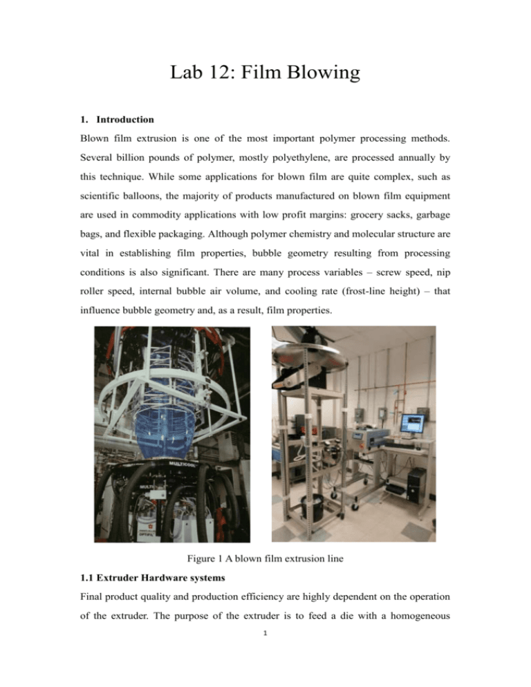
Lab 12: Film Blowing 1. Introduction Blown film extrusion is one of the most important polymer processing methods. Several billion pounds of polymer, mostly polyethylene, are processed annually by this technique. While some applications for blown film are quite complex, such as scientific balloons, the majority of products manufactured on blown film equipment are used in commodity applications with low profit margins: grocery sacks, garbage bags, and flexible packaging. Although polymer chemistry and molecular structure are vital in establishing film properties, bubble geometry resulting from processing conditions is also significant. There are many process variables – screw speed, nip roller speed, internal bubble air volume, and cooling rate (frost-line height) – that influence bubble geometry and, as a result, film properties. Figure 1 A blown film extrusion line 1.1 Extruder Hardware systems Final product quality and production efficiency are highly dependent on the operation of the extruder. The purpose of the extruder is to feed a die with a homogeneous 1 material at constant temperature and pressure. Components of the extruder hardware include drive system, feed system, screw/barrel system, head/die system, and instrumentation and control system. Figure 2 The five extruder hardware systems The drive system supplies the mechanical energy to the polymeric material by rotating the screw. The feed system holds the solid material and delivers it to the extruder. The screw/barrel system has been called the “heart” of the operation. Not only does it melt the solids and pump the polymer through the die, it also prepares the melt to be homogeneous and of constant temperature and pressure. Figure 3 An extruder screw The screw is a long shaft with a flight wrapped helically around it. The barrel is a hollow cylinder extending from the end of the feed throat to the tip of the screw. The head/die system receives the melt stream as it exits the barrel. The die has been called the “brains” of the operation because the product’s final shape is most determined by the melt forming that occurs in the die. 2 Figure 4 A hopper and the extruder screw inside Last but not least, the purpose of the instrumentation and control system is to measure and control important processing parameters. Without the data provided by this system, it would be very difficult to maintain a safe and efficient process and to troubleshoot extrusion problems. Three most important parameters to measure are temperature, head pressure, and motor current. It is common for an extrusion line to be separated into several temperature control zones. The number of zones depends on the length of the barrel, the type of adapter or transfer line to the die, and the size and complexity of the die. While the measurement of extruder head pressure is very important for product quality purposes, it is also the most important measurement from a safety standpoint. Excessive pressure can cause rupture of the barrel, damage to head and die components, and injury to personnel from projected hardware and hot polymer. 1.2 Hardware for Blown Film One of the most important components of the hardware for blown film is the die which is designed to receive polymer melt from the extruder and deliver it to the die exit as a thin annular film, generally exiting the die gap vertically upward. Figure 5 Blown film extruder and die 3 Before talking about other blown film hardware, it is necessary to introduce the bubble geometry because the hardware directly affects the bubble’s geometry. Figure 6 Bubble geometry characteristics The specific shape of the bubble depends on the combined influence of several process parameters. In general, the bubble usually has a small diameter and large thickness at the die exit and transitions to a large diameter and small thickness as it moves upward toward solidification. Above some point, the geometry is frozen and remains virtually constant. Several parameters used to describe the geometry of the bubble include die diameter, die gap, frost-line height, stalk, bubble diameter, film thickness, and layflat width. The die diameter represents the initial bubble diameter as it leaves the die, and the die gap determines the initial bubble wall thickness. As the bubble travels upward from the die face in the molten state, it is cooled and eventually reaches a temperature where it becomes a solid. The distance from the die face to where this solidification takes place is called the frost-line height. Conventionally, the frost line is defined as the lowest point where the bubble is at its maximum diameter because there is effectively no further stretching above this point. The bubble region below the frost line is known as the stalk or neck, particularly when it is relatively long. Above the frost line, where geometry is effectively frozen, the terms bubble diameter and film thickness are simply used for those characteristics. Once the film is collapsed flat and passes through the nip rollers, the two layer web is characterized by a flat width. 4 Figure 7 Nip roller and collapsing frame Moreover, there are several process variables work together to determine the bubble geometry, which are melt speed, nip roller speed, internal bubble volume, and cooling rate. The melt speed is the upward velocity of the polymer as it exits the die gap. It is controlled by the screw speed. The nip roller speed, also called film speed, is the velocity of the polymer as it travels through the nip rollers. The film travels essentially at the nip speed at all points above the frost line. In all cases, the film increases in velocity from the die face, where it travels at the melt speed, to the frost line, where it travels at the nip speed. The internal bubble volume is the amount of air contained inside the bubble between the die face and the nip rollers. The cooling rate is determined by the speed at which the cooling air impinges on the bubble and the temperature of that air. Bubble cooling is generally accomplished by blowing a large volume of air on the film as it exits the die. This may take place on only the outside of the bubble or on both the inside and the outside. Additionally, the bubble is kept inflated to remove more heat from the film as it travels up through ambient air in the cooling tower. As the bubble moves upward and approaches the nip rollers, it is “preflattened” by the collapsing frame. This device provides a smooth transition from a round tube shape to a flattened tube shape. The last part is the nip roller. A pair of nip rollers is located at the top of the cooling tower. Their purpose is to pull the film up from the die. Also, the nip servers as an air seal for the top end of the bubble, so, at least one of the rolls is usually rubber covered. 5 2. Experiment All the processing parameters can be controlled by a computer connected to the blown film extrusion machine. Figure 8 Brabender extruder program 2.1 Experimental procedure 1) Click TEMP to setup the temperature for different control zone. 2) Click EXTR to setup the torque to 5 rpm. A thin annular film will come out of the die slowly. 3) Open the air control valve under the die. Set the pressure of inner air to 0.5 psi and the outer to 5-10 psi. Figure 9 Air cooling valve. 4) Increase the torque gradually but no more than 20-25 rpm. 5) Manually help the extruded film pass through the nip roller. Adjust the speed of nip roller and pressure of cooling air to get uniform film. 6 3. Assignment 1) Investigate the influence of air flow rate and nip roller speed on the thickness of the bag and discuss the relationships between them. 2) Take the film with you, and, outside of lab, identify ways you can test the properties of the films (such as relative elongation and puncture resistance). 3) Compare these properties with a commercially available polymer film. What are the differences between the film you made and the commercially available polymer films (such as garbage bags)? 4. Reference 1) K. Osborn and W. Jenkins, Plastic Films, Technomic, Lancaster, PA (1992) 2) C. Rauwendaal, Understanding Extrusion, Carl Hanser, Munich (1998) 3) Kirk Cantor, Blown Film Extrusion, Hanser Publishers, Munich (2006) 7


