Particle Swarm Optimization Based Intelligent Tuning Of PID
advertisement
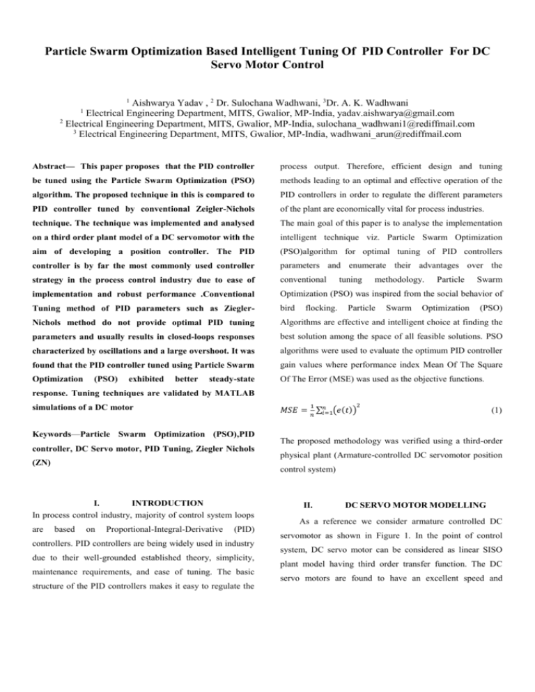
Particle Swarm Optimization Based Intelligent Tuning Of PID Controller For DC Servo Motor Control 1 Aishwarya Yadav , 2 Dr. Sulochana Wadhwani, 3Dr. A. K. Wadhwani Electrical Engineering Department, MITS, Gwalior, MP-India, yadav.aishwarya@gmail.com 2 Electrical Engineering Department, MITS, Gwalior, MP-India, sulochana_wadhwani1@rediffmail.com 3 Electrical Engineering Department, MITS, Gwalior, MP-India, wadhwani_arun@rediffmail.com 1 Abstract— This paper proposes that the PID controller process output. Therefore, efficient design and tuning be tuned using the Particle Swarm Optimization (PSO) methods leading to an optimal and effective operation of the algorithm. The proposed technique in this is compared to PID controllers in order to regulate the different parameters PID controller tuned by conventional Zeigler-Nichols of the plant are economically vital for process industries. technique. The technique was implemented and analysed The main goal of this paper is to analyse the implementation on a third order plant model of a DC servomotor with the intelligent technique viz. Particle Swarm Optimization aim of developing a position controller. The PID (PSO)algorithm for optimal tuning of PID controllers controller is by far the most commonly used controller parameters and enumerate their advantages over the strategy in the process control industry due to ease of conventional implementation and robust performance .Conventional Optimization (PSO) was inspired from the social behavior of Tuning method of PID parameters such as Ziegler- bird Nichols method do not provide optimal PID tuning Algorithms are effective and intelligent choice at finding the parameters and usually results in closed-loops responses best solution among the space of all feasible solutions. PSO characterized by oscillations and a large overshoot. It was algorithms were used to evaluate the optimum PID controller found that the PID controller tuned using Particle Swarm gain values where performance index Mean Of The Square Optimization Of The Error (MSE) was used as the objective functions. (PSO) exhibited better steady-state flocking. tuning methodology. Particle Swarm Particle Optimization Swarm (PSO) response. Tuning techniques are validated by MATLAB 1 simulations of a DC motor 2 𝑀𝑆𝐸 = ∑𝑛𝑖=1(𝑒(𝑡)) 𝑛 Keywords—Particle Swarm Optimization (PSO),PID controller, DC Servo motor, PID Tuning, Ziegler Nichols (ZN) The proposed methodology was verified using a third-order physical plant (Armature-controlled DC servomotor position control system) I. INTRODUCTION In process control industry, majority of control system loops are (1) based on Proportional-Integral-Derivative (PID) controllers. PID controllers are being widely used in industry due to their well-grounded established theory, simplicity, maintenance requirements, and ease of tuning. The basic structure of the PID controllers makes it easy to regulate the II. DC SERVO MOTOR MODELLING As a reference we consider armature controlled DC servomotor as shown in Figure 1. In the point of control system, DC servo motor can be considered as linear SISO plant model having third order transfer function. The DC servo motors are found to have an excellent speed and position control. A simple mathematical relationship between kb back emf constant 0.1 V/rad/sec the shaft agular position ‘ ’ and voltage input ‘ Va (s) ’ to the k m motor torque constant 0.1 N.m/Amp Ra electric resistance DC motor may be derived from physical laws. La electric inductance 2.0 Ohm 0.5 H the overall transfer function of the system is given as: (s) 0.1 (4) Va ( s ) 0.01s 3 0.09 s 2 0.21s III. PID CONTROLLER The PID controller, represented by Figure 3, is well known and widely used to improve the dynamic response as well as to reduce or eliminate the steady state error. The Derivative controller adds a finite zero to the open loop plant Transfer function and improves the transient response. The Integral Figure.1 Schematic Diagram of armature controlled DC controller adds a pole at the origin, thus increasing system type by one and reducing the steady state error due to a step Servo motor function to zero. PID controller consists of three types of control Proportional, Integral and Derivative control . The Over all transfer function of DC servo motor for position control is ( s) Va ( S ) km s[( La s Ra )( Js b) (km kb )] (2) Or km (s) Va ( S ) La Js 3 ( La b Ra j ) s 2 ( Ra b k m k b ) s (3) Here the angular displacement (s ) is considered the output and the armature voltage Va (s) is considered the input. The Figure.3 Block diagram of conventional PID controller block diagram representation is shown in figure 2. The PID controller output relating the error can be described by, t k de(t ) u (t ) k pe(t ) ki e(t )dt d dt 0 (5) Disturbance 𝑇𝑑 Armature 𝟏 (𝑳𝒂𝒔 + 𝑹𝒂) 𝑽𝒂(𝒔) + Load 𝑰𝒂(𝒔) 𝒌𝒎 𝑻𝒎 𝑻𝒍 𝟏 (𝑱𝒔+ 𝑩) 𝑽𝒃(𝒔) 𝑆𝑝𝑒𝑒𝑑 𝟏 𝒔 𝝎(𝒔) Where 𝜽(𝒔) plant) can be expressed by the following transfer function: Various parameters associated with the motor are: b moment of inertia of the rotor motor viscous friction constant ki and are the Proportional, Integral and Derivative gains. In the frequency domain, the relation between the PID controller input e (error signal) and output u (input to the 𝒌𝒃 Figure.2 Block Diagram representation of a DC Servo motor J e(t ) is the error, u (t ) the controller output and kp kd 0.02 kg.m2 0.1 N.m.s k U (S ) (6) k p i kd s E(S ) s The closed loop transfer function is given by, G PID ( S )G( S ) Y (S ) (7) GCL R( S ) 1 G PID ( S )G( S ) The tuning of a PID controller consists of selecting gains Kp, G PID ( S ) Ki and Kd so that performance specifications are satisfied. IV. TUNING OF PID CONTROLLER USING CONVENTIONAL APPROACH A. Conventional Approach - Ziegler Nichols Method Ziegler-Nichols (ZN) method for tuning of PID controllers, though a classic method, has been widely used for the design of various controllers. Ziegler and Nichols presented two methods, a step response method and a frequency response method. In this paper we have employed the frequency response method for tuning of the PID controller. Figure 4 Step Response of DC Motor with ZN Tuned PID B. Implementation of ZN based PID controller In this method, the integral time Ti will be set to infinity and V. PARTICLE SWARM OPTIMIZATION A. Overview the derivative time Td to zero. This is used to get the initial PID setting of the system. Thus the proportional control is selected alone. Increasing the value of the proportional gain until the point of instability is reached (sustained oscillations), gives the critical value of gain, Kc. Thereafter measurement of the period of oscillation of the response is used to obtain the critical time constant, Tc. Once the values for Kc and Tc are obtained, the PID Figure.5 PSO based PID Controller parameters can be calculated, according to the design specifications, as given in Table 1. Further the values of the PID gain coefficients Kp, Ki and Kd for the system described by equation (6), obtained after simulation in MATLAB are Particle swarm optimization (PSO) algorithm is a populationbased evolutionary computation technique developed by the inspiration of the social behaviour in bird flocking or fish schooling. It attempts to mimic the natural process of group given in Table II. communication of individual knowledge, to achieve some TABLE I Ziegler-Nichols PID tuning parameters optimum property. In this method, a population of swarm is initialized with random positions Si and velocities Vi. At the CONTROLLER Kp Ti Td PID 0.6Kc 0.5Tc 0.125Tc beginning, each particle of the population is scattered randomly throughout the entire search space and with the guidance of the performance criterion, the flying particles TABLE II Ziegler-Nichols PID tuning values dynamically adjust their velocities according to their own flying experience and their companions flying experience. Gain Coefficients Kp Ki Kd In PSO, each single solution is a “bird” in the search space; Values 113.4 165.41 19.43 this is referred to as a “particle”. The swarm is modelled as Here, 𝐾𝑖 = 𝐾𝑝 𝑇𝑖 and 𝐾𝑑 = 𝐾𝑝 × 𝑇𝑑 particles in a multidimensional space, which have positions and velocities. These particles have two essential capabilities: From the above formulation the step response of the overall their memory of their own best position and knowledge of system with conventionally Zeigler-Nichols tuned PID the global best [14]. controller is shown in Figure.4. Each particle remembers its best position obtained so far, which is denoted as pbest (𝑃𝑖𝑡 ). It also receives the globally best position achieved by any particle in the population, which is denoted as gbest (𝐺𝑖𝑡 ). The updated velocity of each particle can be calculated using the present velocity and the distances from pbest and gbest as Step 6 Steps 2–5 are repeated until the predefined value of the function or the number of iterations has been given by the following equations: reached. Record the optimized Kp, Ki and Kd 𝑉𝑖𝑡+1 = 𝑊 𝑡 ∙ 𝑉𝑖𝑡 + 𝐶1 ∙ 𝑅1 ∙ (𝑃𝑖𝑡 − 𝑆𝑖𝑡 ) + 𝐶2 ∙ 𝑅2 ∙ (𝐺𝑖𝑡 − 𝑆𝑖𝑡 ) 𝑆𝑖𝑡+1 = 𝑆𝑖𝑡 + 𝑉𝑖𝑡+1 𝑊 𝑡 = (𝑊𝑚𝑎𝑥 − 𝐼𝑡𝑒𝑟) × [ values (8) (9) (𝑊𝑚𝑎𝑥 −𝑊𝑚𝑖𝑛 ) 𝐼𝑡𝑒𝑟𝑚𝑎𝑥 ] (10) Step 7 Perform closed-loop test with the optimised values of controller parameters and calculate the time The updated velocity and the position are given in (8) and domain specification for the system. (9), respectively. Equation (10) shows the inertia weight. If the values are within the allowable limit, consider B. PSO-Based PID Controller Optimization 1) PSO Tuning Parameters The values in the Table III describe the PSO settings used for this work TABLE III PSO Tuning Parameters the current Kp, Ki and Kd values. Otherwise perform the retuning operation for Ki, by replacing the optimized numerical values for Kp and Kd. Figure.6 Shows the optimized values of Kp,Ki and Kd for different iterations PARAMETERS Lower bound [Kp Ki Kd] Upper bound [Kp Ki Kd] Max Iterations Population Size Inertial weight [Wmax,Wmin] VALUES [0 0 0] [5 5 5] 10 120 [0.8,0.4] Acceleration coefficients [c1, c2] [2 2] 2) Step 1 Steps in PSO-Based PID Controller Optimization % Assign values for the PSO parameters % Initialize: swarm (N) and step size; learning rate (C1, C2) dimension for search space (D); inertia (W); Step 2 % Initialize Swarm Velocity and Position % Step 3 Evaluate the objective function of every particle and record each particle’s 𝑃𝑖𝑡 and𝐺𝑖𝑡 . Evaluate the desired optimization fitness function in D-dimension variables. Step 4 Compare the fitness of particle with its 𝑃𝑖𝑡 and replace the local best value as given below. for i=1: N If current fitness (i) < local best fitness (i); Then local best fitness = current fitness; local best position = current position (i); end % same operation to be performed for 𝐺𝑖𝑡 %. Step 5 Figure .6 Change the current velocity and position of the The output response of the system tuned by using PSO-based particle group according to (1) and (2). PID controller is shown in figure 7.The system exhibits very less overshoot comparatively conventionally tuned Zeigler- and setting time are obtained by PSO tuned PID Controller Nichols Method . are a bit on higher side but are in acceptable limit. The comparative output responses of the system tune using PSO-based PID controller and conventionally tuned PID controller using Zeigler Nichols (ZN) method is shown in figure 8. The PSO tuned system shows greatly reduced overshoot Figure.7 Step Response of DC Motor with PSO Tuned PID VI. SIMULATION RESULTS In order to improve the performance of the dc motor under transient and steady state condition, a PID controller is Fig.8 Comparitive step responses for PSO and ZN tuned system inserted in the forward path as shown in Fig 5. The parameters of the PID controller are now adjusted by using conventional method i.e. Ziegler-Nichols method and the response obtained for the DC servomotor is evaluated. Further again the parameters of PID controller are obtained using Artificial Intelligence based PSO Algoriths and the system step responses are evaluated. VII. CONCLUSIONS In this paper, two different control techniques are used for the tuning controller which are, conventional Ziegler Nichols Method and Intelligent control technique(PSO).Application of Intelligent technique (PSO) to the optimum tuning of PID controller led to a satisfactory close-loop response for the system under consideration. The controller tuned using The controller gains were computed by using the classical Zeigler-Nichols rules and Particle swarm optimization. The controller gains obtained from the methods are listed in Table IV. Particle Swarm Optimization (PSO) algorithms resulted in the most satisfactory performance (very less overshoot, minimal rise time).The same Intelligent technique(PSO) can be implemented with the Induction motor drive for analysis TABLE IV Comparison of steady state responses TITLE ZN_PID PSO_PID Rise Time(sec) 0.0813 0.3437 Settling Time (sec) 2.3630 7.1901 % Overshoot 74.40 9.977 Peak Time (sec) 0.2290 1.0998 Kd 19.4353 4.8534 Kp 113.40 3.9353 Ki 165.45 2.1101 of dynamic response . VIII. [1] Dorf and Bishop, Modern Control Systems, 9th Ed., Prentice-Hall, Inc. 2001. [2] Neenu Thomas, Dr. P. Poongodi, Position Control of DC Motor Using Genetic Algorithm Based PID Controller, Proceedings of the World Congress on Engineering 2009 (ISBN: 978-988-18210-1-0) Vol II WCE 2009, July 1 - 3, 2009, London, U.K. [3] Harinath Babu Kamepalli, The optimal basics for Gas, IEEE Potentials, 0278-6648/01/$10.00 © 2001 IEEE, April/May 2001 pp 25-27. Figure 8 shows the corresponding step responses of ZN and [4] Tze-Fun Chan, and Keli Shi, “Applied Intelligent Control of Motor Drives” IEEE Willey Press, First edition, 2011. PSO-based PID systems. It can be clearly seen that PSO tuned system shows improved response with respect to the overshoot as compared to that of ZN tuned system. Rise time REFERENCES . [5] P.C. Krause, "Analysis of Electrical Machinery and Drives System, "IEEE Willey Press, 2000. [6] J. Kennedy and R. Eberhart, “Particle swarm optimization,” in Proc. IEEE Int. Conf. Neural Networks, vol. IV, Perth, Australia, 1995, pp. 1942–1948. [7] Astrom , K.J. and A _ rz_en, K.E. (1993) Expert control, in An Introduction to Intelligent and Autonomous Control(eds P.J. Antsaklis, K.M. Passino, and MA. Norwell) Kluwer Academic Publishers, pp. 163–168. [8] Astrom, K.J. and Bjorn, W. (1995) Adaptive Control, Addison Wesley Publishing Company, Reading, MA. [9] Blashke, F. (1972) The principle of fieldorientation as applied to the new ‘transvektor’ closed-loop control system for rotating-field machines. Simians Review, 34(5), 21–220. [10] Bose, B.K. (1997b) Intelligent control and estimation in power electronics and drives. The 1997 IEEE Internationa lElectric Machines and Drives Conference, USA, May. [11] Bose, B.K., Patel, N.R., and Rajashekara, K. (1997) A neuro fuzzy based on-line efficiency optimization control ofa stator flux oriented direct vector controlled induction motor drive. IEEE Transactions on Industrial Electronics,44, 270–273. [12] Simoes, M.G. and Bose, B.K. (1995) Neural network based estimation of feedback signals for a vector controlled induction motor drive. IEEE Transactions on Industry Applications, 31, 620– 629. [13] M. Molenaar, P. Nijdam, Y. Yan, W.A. Klop, Tuning a PID controller: Particle Swarm Optimization versus Genetic Algorithms, http://www.martinm.nl/attachments/028_paper_ tuning_ a_PID_controller.pdf [14] N. Pillay, “A Particle Swarm Optimization Approach for Tuning of SISO PID Control Loops”, Durban University of Technology, 2008.

