УДК 004.356.2 CONTINUOUS LIQUID INTERFACE PRODUCTION
advertisement
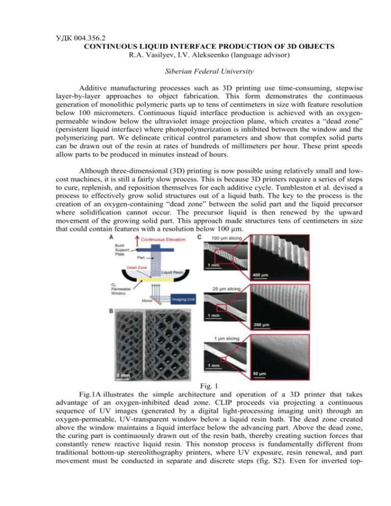
УДК 004.356.2 CONTINUOUS LIQUID INTERFACE PRODUCTION OF 3D OBJECTS R.A. Vasilyev, I.V. Alekseenko (language advisor) Siberian Federal University Additive manufacturing processes such as 3D printing use time-consuming, stepwise layer-by-layer approaches to object fabrication. This form demonstrates the continuous generation of monolithic polymeric parts up to tens of centimeters in size with feature resolution below 100 micrometers. Continuous liquid interface production is achieved with an oxygenpermeable window below the ultraviolet image projection plane, which creates a “dead zone” (persistent liquid interface) where photopolymerization is inhibited between the window and the polymerizing part. We delineate critical control parameters and show that complex solid parts can be drawn out of the resin at rates of hundreds of millimeters per hour. These print speeds allow parts to be produced in minutes instead of hours. Although three-dimensional (3D) printing is now possible using relatively small and lowcost machines, it is still a fairly slow process. This is because 3D printers require a series of steps to cure, replenish, and reposition themselves for each additive cycle. Tumbleston et al. devised a process to effectively grow solid structures out of a liquid bath. The key to the process is the creation of an oxygen-containing “dead zone” between the solid part and the liquid precursor where solidification cannot occur. The precursor liquid is then renewed by the upward movement of the growing solid part. This approach made structures tens of centimeters in size that could contain features with a resolution below 100 µm. Fig. 1 Fig.1A illustrates the simple architecture and operation of a 3D printer that takes advantage of an oxygen-inhibited dead zone. CLIP proceeds via projecting a continuous sequence of UV images (generated by a digital light-processing imaging unit) through an oxygen-permeable, UV-transparent window below a liquid resin bath. The dead zone created above the window maintains a liquid interface below the advancing part. Above the dead zone, the curing part is continuously drawn out of the resin bath, thereby creating suction forces that constantly renew reactive liquid resin. This nonstop process is fundamentally different from traditional bottom-up stereolithography printers, where UV exposure, resin renewal, and part movement must be conducted in separate and discrete steps (fig. S2). Even for inverted top- down approaches in which photopolymerization occurs at an air-resin interface (i.e., the part is successively lowered into a resin bath during printing), these steps must be conducted sequentially for the formation of each layer. Because each step takes several seconds to implement for each layer, and because each layer of a part has a typical thickness of 50 to 100 μm, vertical print speeds are restricted to a few millimeters per hour. By contrast, the print speed for CLIP is limited by resin cure rates and viscosity (discussed below), not by stepwise layer formation. For example, the gyroid and argyle structures shown in Fig. 1B were printed at 500 mm/hour, reaching a height of ~5 cm in less than 10 min (movies S1 and S2). An additional benefit of a continual process is that the choice of 3D model slicing thickness, which affects part resolution, does not influence print speed, as shown in the ramp test patterns in Fig. 1C. Because CLIP is continuous, the refresh rate of projected images can be increased without altering print speed, ultimately allowing for smooth 3D objects with no model slicing artifacts. Fig.2 The dead zone is created by oxygen permeation through the window in Fig. 2. Dead zone thickness is shown as a function of incident photon flux. When pure oxygen is used below the gas-permeable window, the dead zone thickness increases. When nitrogen is used, the dead zone vanishes, resulting in adhesion of the cured resin to the window. Error bars represent SD of 10 measurements of the same conditions. Fig. 3 Thus, using this process control framework, Fig.3 shows an array of expediently produced parts ranging in size from undercut micro paddles with stem diameters of 50 μm (Fig. 3A) to full-size shoe cleats 25 cm in length (Fig. 3C). The Eiffel Tower model illustrates that fine detail is achieved even in macroscale parts (Fig. 3B): The horizontal railing posts (diameter <500 μm) are resolved on this 10-cm-tall model. This ratio of scales (1:200) confirms that the CLIP process enables rapid production of arbitrary microscopic features over parts having macroscopic dimensions. For these parts, the speed-limiting process is resin curing; however, for other part geometries, the speed-limiting process is resin flow into the build area. For such geometries with comparatively wide solid cross sections, parameters that affect resin flow (e.g., resin viscosity, suction pressure gradient) become important to optimize.


