EE * 470 Fundamentals of Biomedical Engineering
BME – 353 Biomedical Measurement and Instrumentation
Experiment on Familiarization with the Wheatstone Bridge
1.
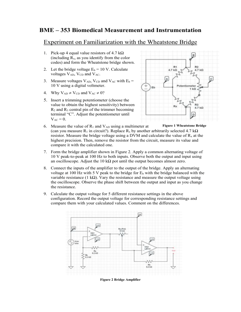
Pick-up 4 equal value resistors of 4.7 kΩ
(including R x
, as you identify from the color codes) and form the Wheatstone bridge shown.
2.
Let the bridge voltage E b
= 10 V. Calculate voltages V
AD
, V
CD
and V
AC
.
3.
Measure voltages V
AD
, V
CD
and V
AC
with E b
=
10 V using a digital voltmeter.
4.
Why V
AD
V
CD
and V
AC
0?
5.
Insert a trimming potentiometer (choose the value to obtain the highest sensitivity) between
R
2
and R
3
central pin of the trimmer becoming terminal “C”. Adjust the potentiometer until
V
AC
= 0 .
6.
Measure the value of R
1
and V
AD
using a multimeter at the highest precision possible
(can you measure R
1
in circuit?). Replace R x
by another arbitrarily selected 4.7 kΩ resistor. Measure the bridge voltage using a DVM and calculate the value of R x
at the highest precision. Then, remove the resistor from the circuit, measure its value and compare it with the calculated one.
7.
Form the bridge amplifier shown in Figure 2. Apply a common alternating voltage of
10 V peak-to-peak at 100 Hz to both inputs. Observe both the output and input using an oscilloscope. Adjust the 10 kΩ pot until the output becomes almost zero.
8.
Connect the inputs of the amplifier to the output of the bridge. Apply an alternating voltage at 100 Hz with 5 V peak to the bridge for E b
with the bridge balanced with the variable resistance (1 kΩ). Vary the resistance and measure the output voltage using the oscilloscope. Observe the phase shift between the output and input as you change the resistance.
9.
Calculate the output voltage for 5 different resistance settings in the above configuration. Record the output voltage for corresponding resistance settings and compare them with your calculated values. Comment on the differences.
Figure 2 Bridge Amplifier
