Forced oscillations of a non-linear electrical series
resonant circuit – chaotic oscillation
TEP
4.5.03
-01
Related Topics
oscillating circuit, forced oscillation, diode, period multiples, Fourier spectrum, chaotic oscillation
Principle
A sinusoidal voltage is applied to a non-linear circuit with a silicon diode functioning as voltageindependent capacity. The oscillating circuit, i.e. the occurrence of chaotic oscillatory behaviour with increasing amplitude is studied.
Material
1 Cobra3 Basic Unit, USB
12150-00
1 Connector, T type, BNC
07542-21
1 Cobra3 power supply
12151-99
1 Adapter, BNC socket, 4 mm socket pair
07542-26
1 Data cable USB
14608-00
1 Adapter, BNC socket, 4 mm plug pair
07542-27
1 Software Cobra3, Frequency Analysis
14514-61
1 Connecting cord, blue, l = 100 mm
07359-04
1 Digital function generator
13654-99
2 Connecting cord, red, l = 250 mm
07360-01
1 Oscilloscope, 30 MHz, 2 channels
11459-95
2 Connecting cord, red, l = 500 mm
07361-01
1 Connection box
06030-23
2 Connecting cord, blue, l = 500 mm
07361-04
1 Coil, 1200 turns
06515-01
1 Screened cable, BNC, l = 250 mm
07542-10
1 Clamping holder
06049-15
1 Screened cable, BNC, l = 750 mm
07542-11
1 Connecting plug
39170-00
1 PC,
Windows®
95 or higher
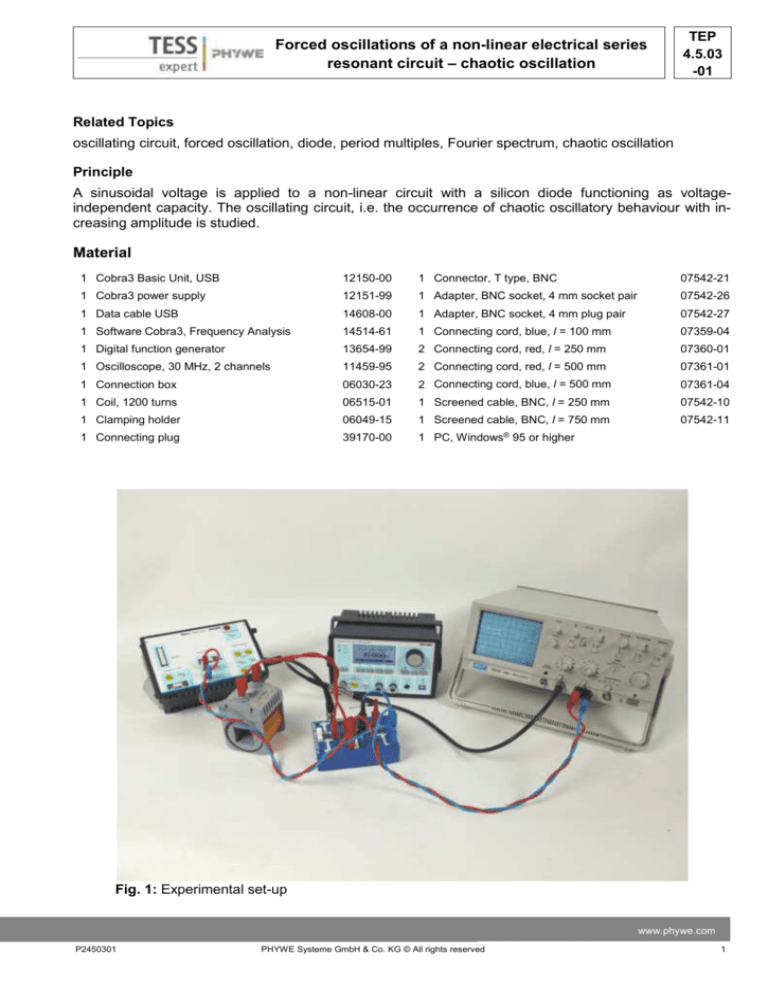
Fig. 1: Experimental set-up
www.phywe.com
P2450301
PHYWE Systeme GmbH & Co. KG © All rights reserved
1
TEP
4.5.03
-01
Forced oscillations of a non-linear electrical series
resonant circuit – chaotic oscillation
Tasks
Study the oscillatory behaviour of the non-linear circuit for an exciting signal with amplitudes between 0.1
and 15 V at frequency of 35 kHz.
Investigate the oscillatory image and the Fourier spectrum as functions of the excitation amplitude. Show
that period multiples and regions of chaotic oscillatory amplitude occur with increasing amplitude.
Fig. 2: Example circuit. Blue cables are grounding connections.
Set-up
Set up the series circuit according to Figs. 1 and 2. The input voltage is tapped off at the diode and fed to
the ANALOG IN 2 (+,-) input jacks of the Cobra3 Basic Unit and the oscilloscope channel CH2. Connect
the circuit with the power output of the digital function generator. Take care to connect the ground to the
diode. Use the T connection to connect the power output with the oscilloscope input jack CH2, too.
Procedure
Use a sinusoidal voltage signal as input with amplitude of 0.1 V. For all measurements use a frequency
of 35 kHz.
Activate the Frequency Analysis program module. Choose the continuous measuring mode and the
maximum frequency range. For each measurement set the voltage range to an appropriate value.
In the course of this experiment increase the input voltage of the digital function generator progressively
from 0.1 to the maximum value in appropriate steps. Observe both signals on the oscilloscope and the
PC screen and record both the signal and the Fourier spectrum for each step. For regions of chaos record several spectra for the same amplitude in order to verify that the occurring fundamental frequencies
vary in number and value.
2
PHYWE Systeme GmbH & Co. KG © All rights reserved
P2450301
Forced oscillations of a non-linear electrical series
resonant circuit – chaotic oscillation
TEP
4.5.03
-01
Fig. 3: schematic circuit
Theory
As a first approximation, the characteristic of a diode behaves quadratic with amplitude of the input signal. The diode’s barrier layer, which is responsible for its capacitance, changes as a function of the applied voltage and the voltage’s sign. Due to the quadratic characteristic line, the behaviour becomes nonlinear. This is responsible for the onset of chaos. This behaviour can be described by a bifurcation diagram, which is based on a quadratic function. In Fig. 4 such a diagram is shown which describes the
“path to chaos” for this experiment. The x-axis shows the increasing voltage of the input signal, the yaxis denotes the frequencies. For an increased voltage an increasing quantity of frequencies may be observed. After exceeding a certain threshold the behaviour of the oscillating circuit can no longer be predicted – it behaves chaotically.
Fig. 4: Logarithmic bifurcation diagram
www.phywe.com
P2450301
PHYWE Systeme GmbH & Co. KG © All rights reserved
3
TEP
4.5.03
-01
Forced oscillations of a non-linear electrical series
resonant circuit – chaotic oscillation
The theory clearly predicts islands of order in chaos, i.e. for certain input amplitudes the system suddenly oscillates in a non-chaotic manner (see Fig. 4). Generally, however, all of such systems ultimately drift
permanently into chaos when the excitation amplitude has increased sufficiently. Spectral analysis is extremely appropriate for the analysis of the occurring oscillation modi.
Note:
The fundamental theoretical framework for chaos theory can naturally not be presented here. However, it
has been exhaustively explained in many publications:
P.S. Lindsay, Period doubling and chaotic behaviour in a driven harmonic oscillator, Phys. Rev. Lett. 47
(1981), p. 1349
W. Lauterborn, W. Meyer-Ilse, Chaos, Physik in unserer Zeit 17 (1986), p. 177
M. Massoth, R. Mettin: Untersuchungen am nichtlinearen RLC-Schwingkreis, Junge Wissenschaft 2
(1987), p. 26
A. May, Anwendungen der Spektrumanalyse zur Auswertung von physikalischen Schulexperimenten
Praxis der Naturwissenschaften – Physik, 36 (1987), p. 15
Evaluation and results
In the following the evaluation of the obtained values is described with the help of example values. Your
results may vary from those presented here.
At very low voltages the diode does not show its rectifying effect and functions as a pure capacitance.
Accordingly, the circuit oscillates like the generator, namely sinusoidal as shown in Fig. 5. Only a single
line appears in the Fourier spectrum at the frequency of 35.2 kHz which corresponds to the natural frequency of the oscillating circuit. With further increased amplitude of the exciting signal the diode only allows a single half-wave of the alternating signal to pass (Fig. 6). According to the theory of Fourier analysis, this means a spectrum with discrete harmonic lines whose lowest frequency is the fundamental oscillation. These conditions of the oscillatory circuit are far to the left in the bifurcation diagram in Fig. 4.
Fig. 5: Voltage tapped off the diode at 𝑼𝑺𝑺 = 𝟎. 𝟏 V. The circuit oscillates sinusoidally as the diode is
functioning as pure capacitance.
4
PHYWE Systeme GmbH & Co. KG © All rights reserved
P2450301
Forced oscillations of a non-linear electrical series
resonant circuit – chaotic oscillation
TEP
4.5.03
-01
Fig. 6: Voltage tapped off the diode at 𝑈𝑠𝑠 = 1.0 𝑉. The di-ode now shows its rectifying effect.
In Fig. 7 the oscillating circuit exhibits the behaviour occurring in the bifurcation diagram at the first fork.
On the oscilloscope screen one signal of higher amplitude and one of lower amplitude are alternately
displayed (depending on the trigger settings). This corresponds to a period doubling: the 17.6 kHz line
appears in the spectrum as the fundamental frequency.
Fig. 7: Voltage tapped off the diode at 𝑈𝑠𝑠 = 3.0 𝑉.. The first period doubling appears. The fundamental
frequency is halved.
In Fig. 8 an additional period doubling occurs. The fundamental frequency of the spectrum is now at
8.8 kHz. On the oscilloscope screen a continually increasing ramification of the periodicity is observed
with every additional increase of signal amplitude. In the bifurcation diagram the second splitting has
been reached.
www.phywe.com
P2450301
PHYWE Systeme GmbH & Co. KG © All rights reserved
5
TEP
4.5.03
-01
Forced oscillations of a non-linear electrical series
resonant circuit – chaotic oscillation
Fig. 8: Voltage tapped off the diode at 𝑈𝑠𝑠 = 7.0 𝑉.. The second period doubling (period quadrupling) appears. The fundamental frequency is a quarter of the natural frequency.
Fig. 9: Voltage tapped off the diode at
𝑈𝑠𝑠 = 9.0 𝑉.. The cir-cuit is now oscillating chaotically.
In Fig. 9 the chaotic status has been achieved. Due to the rectifying effect of the diode, harmonic lines
still appear in the Fourier spectrum, but in contrast to the cases above frequencies between these lines
appear continuously with changing partial amplitudes. The shape of the Fourier spectrum changes continuously and no two identical measurements for the same signal amplitude can be taken. The circuit oscillates with all the displayed frequencies – thus chaotically. The chaotic character of the oscillations also
becomes clear when regarding the amplitudes of the recorded signal. Quite obviously, there is no periodicity at all in the sequence of the signal heights.
6
PHYWE Systeme GmbH & Co. KG © All rights reserved
P2450301
Forced oscillations of a non-linear electrical series
resonant circuit – chaotic oscillation
TEP
4.5.03
-01
Fig. 10: Voltage tapped off the diode at 𝑼𝑺𝑺 = 𝟏𝟔. 𝟎 V. The circuit is in an “island of order”.
In Fig. 10 the oscillator has left the chaotic state for 𝑼𝑺𝑺 = 𝟏𝟔. 𝟎 V. These islands of order are also predicted by the bifurcation diagram. Only the first fundamental and its higher harmonics show in the spectrum. The amplitudes of the signal are periodic. With further increase of the input signal the oscillator will
slip back into chaos.
Remarks on experimental procedure
If the circuit in Fig. 3 is expanded according to the circuit diagram in Fig. 11, it is possible to hear the signals of the oscillators over a loudspeaker. To achieve this, the signal is tapped between the coil and the
diode over a 1 kΩ resistor (39104-41) and led to a LF amplifier (13625-93). From the amplifier the signal
passes to the loudspeaker (13765-00). A frequency between 8 and 9 kHz should be chosen for this experiment. At this frequency, the experiment does not follow the bifurcation diagram as at a frequency of
35 kHz. However, with the loudspeaker it is possible to make the period doubling (or frequency bisection) phenomenon audible.
The oscillator described here was experimentally investigated for the first time by Lindsay in 1981 (theory section and the given literature therein).
Fig. 11: Circuit diagram for acoustic reproduction of the occurring oscillations.
www.phywe.com
P2450301
PHYWE Systeme GmbH & Co. KG © All rights reserved
7


