Assigment 2 - UniMAP Portal
advertisement
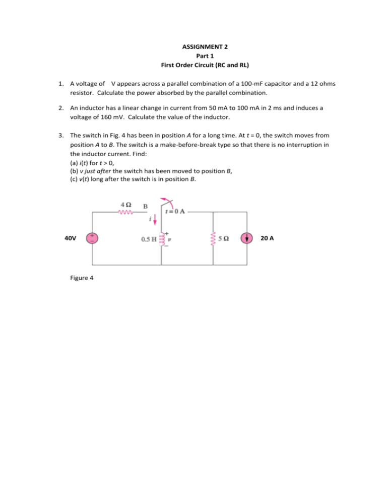
ASSIGNMENT 2 Part 1 First Order Circuit (RC and RL) 1. A voltage of V appears across a parallel combination of a 100-mF capacitor and a 12 ohms resistor. Calculate the power absorbed by the parallel combination. 2. An inductor has a linear change in current from 50 mA to 100 mA in 2 ms and induces a voltage of 160 mV. Calculate the value of the inductor. 3. The switch in Fig. 4 has been in position A for a long time. At t = 0, the switch moves from position A to B. The switch is a make-before-break type so that there is no interruption in the inductor current. Find: (a) i(t) for t > 0, (b) v just after the switch has been moved to position B, (c) v(t) long after the switch is in position B. 40V Figure 4 20 A 4. The inductors in Fig. 5 are initially charged and are connected to the black box at t = 0. If i1(0) = 4 A, i2(0) = -2 A, and v(t) = 50e-200t mV, t 0$, find: (a). the energy initially stored in each inductor, (b). the total energy delivered to the black box from t = 0 to t = , (c). i1(t) and i2(t), t 0, (d). i(t), t 0. Figure 5 5. In the circuit shown in Fig. 6 v(t)=56e-200t V, t>0 i(t)=8e-200t mA, t >0 (a) Find the values of R and C. (b) Calculate the time constant (c) Determine the time required for the voltage to decay half its initial at t=0. i + R v – Figure 6 C 6. Find the time constant for the RC circuit in Fig. 7 Figure 7 7. Determine the time constant for the circuit in Fig. 8 10 k 20 k 100 pF 40 k 30 k Figure 8 8. The switch in Fig. 9 moves instantaneously from A to B at t=0. Find v for t>0. 5 k A + _ B 10 F + 40 V v 2 k Figure 9 9. The switch in Fig. 10 has been closed for a long time, and it opens at t = 0. Find v(t) for t 0. v(t) Figure 10 10. Assuming that the switch in Fig. 11 has been in position A for a long time and is moved to position B at t=0, find vo(t) for t 0. 20 k t=0 B + A _ + 2 mF 12 V vo 40 k 20 k– Figure 11 11. The switch in Fig. 12 opens at t=0. Find vo for t > 0. 2 k t=0 + + _ 6V vo – 4 k Figure 12 50 μF 12. For the circuit in Fig. 13, find io for t >0. 3 t=0 4H io + _ 4 8 24 V Figure 13 13. Calculate the time constant of the circuit in Fig. 14 20 k 10 k 5 mH 40 k Figure 14. 30 k Part 1 Assignment for RLC 1. 2. 3. Formulate the differential equation for the series RLC circuit Formulate the differential equation for the parallel RLC circuit If R = 20 ohms, L = 0.6 H, what value of C that will make an RLC series circuit : a. Overdamped b. Critically damped c. Underdamped 4. For series RLC circuit with R = 2 and L = 1 H, analyse the resonant frequency, o for each C (where C = 1 F, C = 0.5 F and C = 2 F). 5. The switch in the circuit of Figure 1 has been closed for a long time but is opened at t = 0. Figure 1 a. Find values of and o. b. Define its characteristic equation. c. Determine i(t) for t>0. 6. For the circuit shown in Figure 2, find Figure 2 7. For RLC circuit in Figure 3 below : Figure 3 a. Find values of and o. b. Define its characteristic equation. c. Determine i(x) and VR for t>0.

