PRP - Edge
advertisement
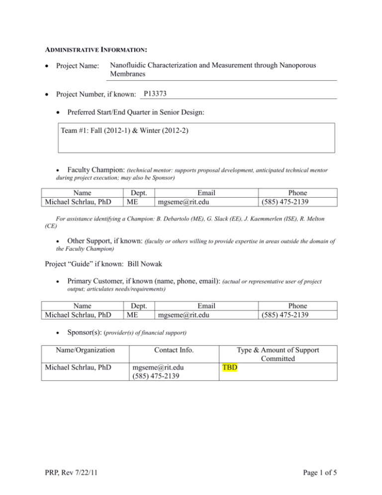
ADMINISTRATIVE INFORMATION: Project Name: Project Number, if known: Nanofluidic Characterization and Measurement through Nanoporous Membranes P13373 Preferred Start/End Quarter in Senior Design: Team #1: Fall (2012-1) & Winter (2012-2) Faculty Champion: (technical mentor: supports proposal development, anticipated technical mentor during project execution; may also be Sponsor) Name Michael Schrlau, PhD Dept. ME Email mgseme@rit.edu Phone (585) 475-2139 For assistance identifying a Champion: B. Debartolo (ME), G. Slack (EE), J. Kaemmerlen (ISE), R. Melton (CE) Other Support, if the Faculty Champion) known: (faculty or others willing to provide expertise in areas outside the domain of Project “Guide” if known: Bill Nowak Primary Customer, if known (name, phone, email): (actual or representative user of project output; articulates needs/requirements) Name Michael Schrlau, PhD Dept. ME Email mgseme@rit.edu Phone (585) 475-2139 Sponsor(s): (provider(s) of financial support) Name/Organization Michael Schrlau, PhD PRP, Rev 7/22/11 Contact Info. mgseme@rit.edu (585) 475-2139 Type & Amount of Support Committed TBD Page 1 of 5 Nanofluidic Characterization and Measurement through Nanoporous Membranes PROJECT SUMMARY The goal of the project is to develop a means to characterize and measure nanofluidic flow through membranes consisting of many nanoscale channels. The objectives of the project will to design, construct, and test a flow measurement system for commercially available nanoporous membranes. The developed instrument will provide needed quantitative fluid flow measurements at the nanoscale and immediately impact the nanobiotechnology research and educational activities within RIT’s Nano-Bio Interface Laboratory (NBIL). INTRODUCTION AND MOTIVATION Studies of fluid flow in small diameter capillaries gained attention early on. Poiseuille (1846) carried out his seminal experiments with glass capillaries with diameters as small as 29µm. Likewise, of considerable interest are the characteristics of the fluid flow through capillaries of even smaller diameter since it has been predicted that, at some point, fluid behavior deviates from classical continuum behavior. For this reason, nanostructures, specifically carbon nanotubes (CNTs), are attractive for fluidic studies at extremely small scales. Sinha et al. (2007) carried out flow measurements through carbon nanopipes produced with alumina membrane templates. Here, a two-drop technique was used to obtain flow rate as a function of the pressure drop and the results were compared with theoretical predictions to obtain the apparent viscosity of the liquid. However, the task of measuring the flow rate through a single nanopipe is quite challenging and time consuming. Using the two drop technique, Sinha et al. (2007) carried out experiments with tubes as small as 60nm in diameter and did not observe any significant deviations from classical behavior. In other words, the liquid respected the non-slip boundary condition at the solid boundaries. To overcome the difficulties of studying fluid flow through individual tubes, many researchers have carried out flow rate measurements with both naturally occurring and synthetic membranes rather than individual tubes. Debye and Cleland (1959) and Anderson and Quinn (1972) used, respectively, porous Vicor glass and polymer, track-etched membranes. More recently, Hinds et al. (2004) and Majumder et al. (2005) carried out liquid flow measurements and observed flow rates four to five orders of magnitude greater than predicted based on accepted values of bulk viscosity and the non-slip condition. In a similar set of experiments, Holt et al. (2006) grew double-walled, carbon nanotubes with inner diameters of about 2 nm on silicon substrate patterned with catalyst particles and found water flow rates were 560-8400 times the values predicted by classical theory. Bau et al. (2004) and Lauga et al. (2005) both review these experiments and summarize the available data in tables that include the reported slip lengths. More recently, Whitby and Quirke (2007) review fluid flow in CNTs and discuss possible applications. The available experimental data indicates significant differences in liquid flow behavior at the nanoscale. These striking differences in behavior are most likely due to the differences in morphology and properties. However, more testing is needed, thus the motivation for this project. PROJECT OBJECTIVES The two main objectives of this project are to (1) design an instrument to measure fluid flow through commercially available nanoporous membranes, (2) build the measurement system, and (3) test and compare the measurements to results obtained previously and theoretical predictions. PRP, Rev 8/20/11 Page 2 of 5 DETAILED PROJECT DESCRIPTION A. Customer Needs and Objectives Customer Need # Import ance CN 1 CN 2 CN 3 CN 4 CN 5 CN 6 CN 7 CN 8 CN 9 CN 10 CN 11 CN 12 CN 13 CN 14 CN 15 CN 16 CN 17 CN 18 CN 19 CN 20 CN 21 1 1 1 1 3 1 1 1 1 1 2 1 1 2 1 1 3 2 3 3 2 Description Portable to move between different platforms and easy to setup User friendly and easy to operate Easy to maintain System must have hard piping System must have a frame Compatible with different membrane sizes Capability to bleed the system to eliminate air bubbles or exchange fluid Measuring the pressure before and after the membrane Measuring the temperature before and after the membrane Measuring the flow rate before and after the membrane Real time visualization of the data (Pressure, Temperature and Flow Rate) Storing and manipulating the visualized data Easy to assemble and disassemble Electronically automated pressure driven flow Ability to visualize the membrane Ability to inject secondary fluid into primary flow stream Able to fit under microscope Software is RIT owned, custom developed or readily available freeware Ability to acquire selected measurements Ability to compare selected measurements Adjustable Sampling rate B. Functional Decomposition TBD C. Potential Concepts The recommended path forward for the project team is to (1) identify the main components in the project and how they need to interface, (2) divide up the work to tackle the main components individually keeping in mind how they interface with each other, (3) bring them together and interface when appropriate at different development stages (e.g. initial interfacing early on to quickly identify key problems areas, then subsequent interfacing to refine integration). Regardless, the team will need to plan and time individual component activities and systems integration to be successful. PRP, Rev 7/22/11 Page 3 of 5 Nanofluidic Characterization and Measurement through Nanoporous Membranes D. Specifications Source S1 S2 S3 S4 S5 S6 S7 S8 S9 S 10 S 11 Functi on CN 6 All CN 8 CN 8 CN 10 CN 10 CN 9 CN 9 CN 21 CN 21 Specification (metric) Unit of Measure Marginal Value Ideal Value Test rig size limit (l x w x h) Membrane diameter Development cost Measuring pressure range Measuring pressure accuracy Measuring flow rate range Measuring flow rate accuracy Measuring temperature range Measuring temperature accuracy Fine sampling rate Coarse sampling rate mm mm $ kPa Pa mL/min femtoliter/s ᵒC ᵒC per second per minute 200x120x100 13 - 25 < 2,500 < 500 0.1 0 - 10 1 -20 - 100 0.01 100 1 S1 S2 S3 S4 S5 S6 S7 S8 S9 S 10 S 11 E. Constraints 1) Developed system consists of its own parts (i.e., does not require NBIL parts to operate). 2) Project will need to purchase the commercially available membranes for testing. 3) Training must be completed before handling any high-cost instrumentation, including the optical microscope or compressed gas cylinders. F. Project Deliverables 1) A functioning measurement system. 2) Report detailing all design and development processes, highlighting the end design and future improvements. 3) A Manual detailing all design components, manufacturer and part numbers of third party items, the function and operation of each component and key contacts for future questions. 4) Tutorial guide to intuitively instruct others on how to use the designed tool. 5) Design and project reviews. 6) Attendance by at least one group member to the 2013 Imagine RIT to showcase the system. G. Budget Estimate $2,500 H. Intellectual Property (IP) considerations Any IP generated as a result of this project will belong to RIT and its inventers. I. Other Information PRP, Rev 8/20/11 Page 4 of 5 None J. Continuation Project Information None STUDENT STAFFING Discipline ME How Many? 3-4 Anticipated Skills Needed Responsible for designing the fluidic systems and measurement approach as well as choosing appropriate components and sensors. Will be constructing the system and testing its capabilities. Will be conducting actual measurements and comparing to reported results. Will need to predict classical fluid behavior throught the porous membrane and compare these predicts to their experimental results. Anticipated skills include, CAD, MatLAB, LabView, data acquisition, comfort with hydraulics and/or piping. OTHER RESOURCES ANTICIPATED Category Resource Available? Description Faculty Environment MSD Design Center Machine Shop & Brinkman lab Nano-Bio Interface Laboratory (NBIL, Schrlau’s Laboratory) Equipment Inverted Microscope (NBIL) Upright Microscope (NBIL) Materials Various materials and accessories (NBIL) Other Technical Expertise (Microscopy and manipulator – Schrlau, Piezoelectric actuators - New Scale Technologies) Prepared by: PRP, Rev 7/22/11 Michael Schrlau Date: 08/25/2012 Page 5 of 5

