glass
advertisement
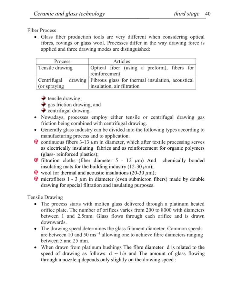
Ceramic and glass technology third stage Fiber Process Glass fiber production tools are very different when considering optical fibres, rovings or glass wool. Processes differ in the way drawing force is applied and three drawing modes are distinguished: Process Tensile drawing Articles Optical fiber (using a preform), fibers for reinforcement Centrifugal drawing Fibrous glass for thermal insulation, acoustical (or spraying insulation, air filtration tensile drawing, gas friction drawing, and centrifugal drawing. Nowadays, processes employ either tensile or centrifugal drawing gas friction being combined with centrifugal drawing. Generally glass industry can be divided into the following types according to manufacturing process and to application. continuous fibers 3-13 𝜇m in diameter, which after textile processing serves as electrically insulating fabrics and as reinforcement for organic polymers (glass- reinforced plastics); filtration cloths (fiber diameter 5 - 12 𝜇m) And chemically bonded insulating mats for the building industry (12-30 𝜇m); wool for thermal and acoustic insulations (20-30 𝜇m); microfibers I - 3 𝜇m in diameter (even submicron fibers) made by double drawing for special filtration and insulating purposes. Tensile Drawing The process starts with molten glass delivered through a platinum heated orifice plate. The number of orifices varies from 200 to 8000 with diameters between 1 and 2.5mm. Glass flows through each orifice and is drawn downwards. The drawing speed determines the glass filament diameter. Common speeds are between 10 and 50 ms -1 allowing one to achieve fibre diameters ranging between 5 and 25 mm. When drawn from platinum bushings The fibre diameter d is related to the speed of drawing as follows: d ~ 1/𝜐 and The amount of glass flowing through a nozzle q depends only slightly on the drawing speed : 40 Ceramic and glass technology third stage where q is the volume rate of flow, h is the height of glass above the nozzle, r is the internal nozzle radius, l is the nozzle length, v is kinematic viscosity of glass in the nozzle and k is a constant. Rovings are produced by combining several hundred fibres (range 100–2000 filaments). Several fibres are drawn in parallel and gathered as shown in Fig. 1. Antiabrading treatment is then essential for keeping excellent mechanical resistance. Surface treatment also called sizing is required for adhesion to the matrix in the case of composites. Figure 1 illustrates the manufacturing of multi-fibres and the application of sizing. In a typical fibre-forming machine the coating applicator is located just below the fibre-forming bushing. Glass fibres leave the forming die at a temperature over 1000 °C and are rapidly quenched to deposition temperature (at 100 °C) by the aqueous sizing solution. Since the fibres are drawn under high speeds only short times (about 5ms for a drawing speed of 1000mmin -1) are available for applying the sizing. The filaments are then formed into a multifilament strand and wound into a package. A number of compositions are used to produce fiberglass. Insulation fibers are produced from modified soda-lime-silica compositions, which contain more alumina and iron than container glasses. Most of the continuous fiberglass is produced from so-called E glass, S (for strong) glass and C (for corrosion-resistant) glass. S glass contains more alumina than E glass, while C glass contains more silica and less alumina than E glass. Coatings play an essential role in the manufacturing of products made from glass fibre. Because of its abrasiveness, glass fibre would be useless if not coated during the sizing operation. In fact, without the protective coating the fibre loses its strength and destructs . Sizing not only increases durability, but also adds significant value to the product. Although glass composition is tailored according to applications, sizing is the most important factor in differentiating one fibre product from another. The wide variety of fibre glass applications leads to more than 100 sizing compositions on the market, each containing from 2 to 10 components. All sizings are aqueous chemical solutions containing 0.05–10%solids.Water has a key role in the technology. In fact, while it carries and dilutes solid components, it also cools the hot fibre allowing for the deposition of solids. 41 Ceramic and glass technology third stage These are composed of the film former (polymer), the coupling agent allowing adhesion of the film with the fibre, lubricants, antistatic compounds and antioxidants. Fig 1 Optical fibres require refractive index gradient necessary to propagate the optical beam. Different routes exist to generate a fibre with either discontinuously or continuously varying index. When a discontinuously changing index is to be fabricated, a preform can be made assembling an internal core of larger refractive index and an external tube made of a glass of lower refractive index. The diameter of the rod should be just slightly less than the inner diameter of the tube. After placing the rod inside the tube, the ensemble is heated to fuse the two glasses to form a unit. This preform is then drawn to produce very fine fibres (Fig. 2). Again the fibres are protected against abrasion by a polymer membrane. a double crucible can be used to produce the two glasses that are further drawn to form the fibre. 42 Ceramic and glass technology third stage Fig 2 Centrifugal Drawing Fibres used in glass wool and mats have to be chopped. Also, the surface treatment will control the performance in use. The process again starts with the glass delivery from a furnace. Glass with low viscosity melt is dropped onto rotating cylinders spinning at an elevated velocity around their horizontal axis. Glass drops are projected from one cylinder to another before producing fibres of different lengths and reaching a moving belt downwards where remaining glass drops are aspired. Meanwhile the fibres are sprayed with organic binders with curing happening in the polymerization furnace downstream (Fig 3). the TEL process which supplies most of its glass wool production. The main element is the centrifuge that spins around a vertical axis at 3000 rotations per minute (Fig 4). It is supplied by a unique glass stream. Its flank presents large holes through which glass drops are projected against a circumferential and inclined wall presenting numerous smaller holes (10 000 about 1mm in diameter). Centrifugal drawing is assisted by annealed air blowers (Fig. 10.20). On reaching the moving belt the fibres are sprayed by polymers (protecting the fibres from erosion) further cured downstream. Moving belts allow for a continuous process delivery. 43 Ceramic and glass technology third stage Fig 3 Fig 4 Annealing Annealing of glass is a controlled heat treatment designed to prevent or remove undesirably large internal stresses in glass-ware. Spontaneous stress relief takes place in glass by viscous flow within the annealing range limited by the upper and Lower annealing temperature*; for purposes of 44 Ceramic and glass technology third stage comparison the temperatures are characterized by viscosities of 10 12and 1013 pa.s. At the upper annealing temperate internal stress is substantially relieved within a few minutes, at the lower annealing temperature within a few hours. Formation of internal stress may be illustrated as follows: when a glass plate cooled or heated in a temperature range where the glass behaves as a solid , elastic body (i.e. below the lower annealing temperature) a temperature grad arises between the surface and the internal plate layers. as no free expansion or contraction of these layers can occur according to the respective thermal coefficient, mechanical stresses are created; compression and tensile stresses mutually compensated. The stress is proportional to the temperature differences and the expansion coefficient; maximum stress values at the centre and surface are where E is the elasticity nodules, ∝: is the coefficient of thermal expansion, 𝜇 is Poisson’s ratio, T is the temperature at the plate centre or surface and Tav is the average temperature corresponding to the overall sample size. Similar relationships are available for a variety of geometrical shapes. As soon as the temperatures in the plate are equalized, the type of stress considered so far is relieved, and is therefore called the temporary stress 45 Ceramic and glass technology third stage If the glass is cooled from sufficiently high temperatures where it is still formable, temperatures gradients but no stress will arise as the latter will immediately be relieved by viscous flow. For a constant rate of cooling, it may be assumed that the stress will appear only after complete solidification of the glass at the moment when temperature differences between glass surface and interior begin to equalize. From this moment. the compression stress will increase on the surface and internal stress inside. 46 Ceramic and glass technology third stage The stress will reach a maximum when the temperatures have completely equalized and will remain in the article as a permanent stress. Its distribution in a plate is again parabolic, but it acts in a direction opposite to that of temporary stress and corresponds in size to the stress released by viscous flow where the temperature gradient was formed. Permanent tensile stress will generally arise at points which have been maintained at the highest temperature during cooling. And compression stress will appear at points cooling at the highest rate The occurrence of permanent stress is thus related to glass solidification in the presence of temperature gradients The danger of temporary stress lies in the fact that too fast cooling may bring about fracture when the tensile strength of glass has been exceeded, permanent stress may lead to the same consequence in the final stage of temperature equalization Badly distributed permanent stress, which always includes its tensile component: will reduce the final strength of the ware and thus impair its value. The occurrence of both temporary and permanent stress could be avoided cooling down the glass at such a low rate as to render the temperature gradient negligible however, such a procedure is un acceptable in practice and the aim is find a way of cooling which would allow, with the highest economy, the production of ware with permanent stress within permissible limits, The glass annealing process which meets the above requirements, may be regarded as consisting of several stage Heating the ware. when it has cooled to a lower temperature, to the upper annealing temperature. Holding at the upper annealing temperature for a period required for elimination of temperature gradients and release of the stresses present. Slow cooling within a temperature range in which glass has a viscosity of 1012and 1013 pa s to suppress the formation of permanent stresses. more rapid cooling to ambient temperature at a rate Limited by the formation of temporary stress. The rate of stress relief is well approximate by an empirical equation' as suggested in 1920 ,by Adams and Williamson or1 the basis of their research of optical glass annealing: 𝑑𝜎 𝑑𝑡 or after integration = A𝜎 2 47 Ceramic and glass technology third stage where A is annealing constant which depends on glass composition (viscosity) and is an exponential function of temperature. The AdamsWilliamson equation has been used as a basis for calculating annealing schedules in industrial practice. Determination of the annealing constant and its temperature dependence for a given glass is time consuming and not really necessary; practical use is made of the fact that high initial stresses are relieved to harmless levels within several minutes at a viscosity of 1012 Pa. s corresponding to the upper annealing temperature. Glass is conditioned at this temperature for a period of time required for relieving the stress and eliminating the temperature difference (the usual period required being 5 - 20 minutes). If no precise data on viscosity are available, the upper annealing temperature can be estimated by adding 5-10 C to the Tg (transformation temperature) determined from the curve. The second stage of the annealing process involves cooling in the annealing range. The cooling rate should preclude the formation of permanent stresses The relations between cooling rate and stress have the general form where Ma is a material constant (depending on glass composition and temperature h is the cooling rate 𝛿 is the effective dimension; full plate thickness when cooling from one side, half thickness when cooling from both sides; 𝛿 = r for full sphere, cylinders, while 𝛿equal to the wall thickness (r2-r1) for hollow articles. 𝜁 is dimensionless quantity which is a function of article shape and size; it is obtained solutions of heat transfer in bodies of various symmetries. The value of 𝜁 can be calculated on simple shapes from the heat transfer laws, and determined experimentally for more complex shapes. The values Ma and 𝜁 are then used for calculating the maximum permissible cooling Rate h1 within the annealing range according to eqa: 48 Ceramic and glass technology third stage In order to facilitate control of the specified temperatures, the annealing schedule can be adjusted so that lower cooling rates are applied at the beginning h=2/3 h1, rate h1 in the second stage and h =2 h1 in the last. The overall residence time in the annealing range remains unchanged. Below the lower annealing temperature, the rate of stress relief in glass is already low that permanent stress can no longer occur. The glass can then be cooled at a third to six-fold rate. The annealing schedule is represented graphically by a curve which show the respective lehr temperatures and the calculated cooling rates. The dashed line shows the theoretically calculated schedule while the full lines represent the cooling employed in practice with respect to the possible temperature control the lehr. 49 Ceramic and glass technology third stage Tempering Annealing of glass is a process intended for the elimination of stress, However suitably distributed permanent stress may substantially increase the strength of glass Therefore, in some cases, glass is intentionally cooled at a high rate so that compression stress arises in surface layers the process is called thermal tempering or toughening Toughening carried out by quenching the glass from a temperature close to the softening point using a stream of air from suitably arranged nozzles, or immersion of the object in oil bath or by pressing it in contact with metal surfaces. Toughened glass has superior strength, as fracture results from the effect of tensile (bending) stressing of the surface, If compression stress has been set up in the surface layers, any external force must first overcome this "prestress" before tensile stressing becomes effective. The conditions in a toughened glass plate subjected to external bending stress are show in l4; a permanent internal stress acts against the external force. The degree of toughening is characterized by the specific optical path difference* ∆, corresponding to the maximum tensile stress inside the object wall 𝜎𝑐 here, the relationship holds where ∆ is the path difference in nm cm-1, B is the stress-optical coefficient ( 2.5 x l0-12 Pa-1.), 𝜎𝑐 is tensile stress in Pa . In a toughened plate, the compression stress at the surface is roughly equal to double the tensile stress in the centre plane. In practice, the degree of toughening is expressed by a relative quantity obtained as a multiple of wavelength corresponding to one order ∆𝑟𝑒𝑙 = ∆/540; its numerical value varies in the range 1 to 6. A significant quantity is the so-called toughening temperature: when cooled from this or a higher temperature. permanent stress at a given cooling rate reaches its ;maximum value. Further increase in initial temperature therefore does not change the degree of toughening which depends solely on cooling rate. The toughening temperature for several glasses is shown in Fig. corresponds to the point where the curve bends into the horizontal section. 50 Ceramic and glass technology third stage Toughening of glass is most frequently used with sheet glass intended for vehicle wind screens, building items (e.g. all-glass doors) etc. Toughening is also employ in the manufacture of domestic glass-ware. Toughened glasses cannot used at elevated temperatures. since relaxation of great stresses takes place from 300-400 C upwards. Chemical Tempering of Glass Chemical tempering is applied for special applications like aeroplane and high speed train windshields, requiring high safety levels, and for thin glazing for which conventional thermal tempering would mark the surface or would not allow for sufficient strengthening. Although production yields are much less important, chemical tempering has to be used to achieve very high level of stresses required in the range of 500–600MPa. The treated depth of glass (diffusion length) is reduced to hundreds of micrometers. The glass to be treated is immersed in a salt bath containing cations the radii of which are larger than those to be exchanged in the glass. Ion exchange induces compression at the glazing surface. Generally, the cations are alkali metal ions since they diffuse in glass much more rapidly than any other ions . For instance, a glass containing sodium is strengthened by immersion into a potassium salt bath (generally KNO3). To enhance 51 Ceramic and glass technology third stage diffusion elevated temperatures (400–500 8C) are used for the treatment. 52
