DOCX
advertisement

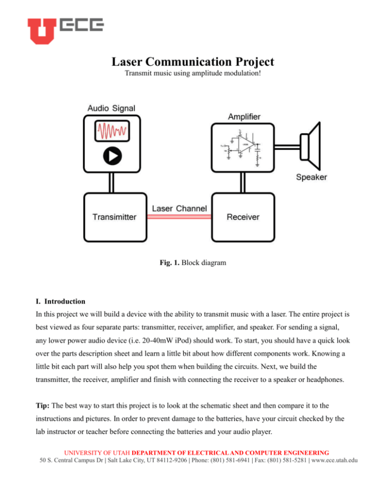
Laser Communication Project Transmit music using amplitude modulation! Fig. 1. Block diagram I. Introduction In this project we will build a device with the ability to transmit music with a laser. The entire project is best viewed as four separate parts: transmitter, receiver, amplifier, and speaker. For sending a signal, any lower power audio device (i.e. 20-40mW iPod) should work. To start, you should have a quick look over the parts description sheet and learn a little bit about how different components work. Knowing a little bit each part will also help you spot them when building the circuits. Next, we build the transmitter, the receiver, amplifier and finish with connecting the receiver to a speaker or headphones. Tip: The best way to start this project is to look at the schematic sheet and then compare it to the instructions and pictures. In order to prevent damage to the batteries, have your circuit checked by the lab instructor or teacher before connecting the batteries and your audio player. UNIVERSITY OF UTAH DEPARTMENT OF ELECTRICAL AND COMPUTER ENGINEERING 50 S. Central Campus Dr | Salt Lake City, UT 84112-9206 | Phone: (801) 581-6941 | Fax: (801) 581-5281 | www.ece.utah.edu II. Using a Breadboard When testing circuits, electrical engineers use the “Breadboard” or 'Proto-board”. The purpose of the breadboard is to provide a quick way to hook up all the components of a circuit for testing purposes. A breadboard typically looks like a plastic rectangle with several holes in its surface (Fig 2). The holes in the top row are all connected by a wire that runs underneath the breadboard. The same applies to the lowest row. In the middle section of a breadboard the holes are connected vertically, but are divided by a line that runs through the middle of the breadboard, the holes above the line are NOT connected to the ones below it. Fig. 2. The breadboard and its connections. III. The Transmitter The transmitter is made up of an inductor, capacitor, laser diode, and audio connector. The circuit can be found on the schematic sheet and a picture of the completed transmitter can be seen in Fig 3. The inductor and capacitor are used to prevent the battery power from masking the audio signal. Normally the battery would immediately compensate for, and override, the audio players signal. The capacitor and inductor absorb and release energy at different rates depending on their size and act as a buffer from the battery. The purpose of the 3 volt battery source is to center the laser at a neutral brightness. Your mp3 player will increase or decrease the brightness of the laser depending on volume and UNIVERSITY OF UTAH DEPARTMENT OF ELECTRICAL AND COMPUTER ENGINEERING 50 S. Central Campus Dr | Salt Lake City, UT 84112-9206 | Phone: (801) 581-6941 | Fax: (801) 581-5281 | www.ece.utah.edu frequency. An interesting analogy can be seen in a water wheel: the constant source of water is like a battery, the audio player is like a control valve, the inductor is the angular momentum of the wheel, and the capacitor is like the buckets. Without angular momentum the wheel would hit maximum speed with the slightest change in water flow. Increasing mass flow with the audio player increases the speed of the wheel. The buckets store different amounts of water depending on their size and total flow of the water. The laser is similar to the output power of the wheel. Inductor and capacitor sizes are very important when dealing with music and determine which frequency components will be passed or absorbed. Fig. 3. The transmitter circuit without a battery connection Laser Light LASER stands for Light Amplification by Stimulated Emission of Radiation. Laser light is a great way to transmit information and especially through fiber optic cables. If you are only sending a signal in a single direction and without obstruction laser light can be used to send very high frequency signals. What makes a laser unique is that it emits light that is concentrated in one direction, contains light centered on a single frequency and wavelength (usually red), and the emitted photons are in phase. AM Modulation In simple terms AM modulation is a wave of a much higher frequency ridding on a lower frequency UNIVERSITY OF UTAH DEPARTMENT OF ELECTRICAL AND COMPUTER ENGINEERING 50 S. Central Campus Dr | Salt Lake City, UT 84112-9206 | Phone: (801) 581-6941 | Fax: (801) 581-5281 | www.ece.utah.edu wave. By ridding, we mean that the total signal is the sum of both the lower and higher frequency signals. AM stands for Amplitude Modulation because the amplitude or height of the higher frequency components is modulated. Light waves have extremely high frequency and audio signals can be used to pulse the laser light. Filters The key to the transmitter is that the inductor and capacitor allow the music signal to be centered on the lasers ideal DC bias (the optimal voltage for powering the laser) without the battery instantly compensating when the audio player drops or increases its potential. A filter is a device that allows and blocks certain ranges of frequency. From the batteries perspective the capacitor and inductor allow low frequency to pass and from the audio signals perspective they allow high frequencies to pass. This may be a difficult concept to understand so don’t be afraid to ask if you have any questions! A B Fig. 4 Filtering circuits A. High pass filter B. Low pass filter Electrical Engineers use frequency analysis everyday and in almost everything they invent. Knowing how your circuit will respond to different signals is a very important concept. For circuits with inductors and capacitors Eq. 1 Cut-off frequencies for both high and low pass filters UNIVERSITY OF UTAH DEPARTMENT OF ELECTRICAL AND COMPUTER ENGINEERING 50 S. Central Campus Dr | Salt Lake City, UT 84112-9206 | Phone: (801) 581-6941 | Fax: (801) 581-5281 | www.ece.utah.edu Keep Fig 4 in mind (where the laser is considered to be like a resistor RL) and after you build the circuit you might be able to understand why the receiver doesn’t have a very good response to bass frequencies. IV. Audio amplifier (optional) Depending on your lab the audio amplifier may be pre-built for you. The amplifier takes more steps to build than the receiver and it is easier to construct it first and then add the receiver after. The audio amplifier comes in an 8 pin IC (Integrated circuit) package and is controlled by external circuitry. The pin numbers start at the top left (indented dot) and increase as you go counter clockwise. If you are feeling brave, you can refer to Fig. 5 to get started and then build it by yourself just using the schematic. If you need more help, Fig. 6 shows exactly how to build it. A B Fig. 5 A. Amplifier schematic B. Getting started Audio amplifiers involve feedback, are made up of lots transistors, and can take a lot of learning/experience to actually understand. Basically an audio amplifier increases the power of a signal so that I can be heard on a speaker. UNIVERSITY OF UTAH DEPARTMENT OF ELECTRICAL AND COMPUTER ENGINEERING 50 S. Central Campus Dr | Salt Lake City, UT 84112-9206 | Phone: (801) 581-6941 | Fax: (801) 581-5281 | www.ece.utah.edu Fig. 6 The entire amplifier circuit V. The Receiver and Demodulator The receiver is a simple circuit to build and is easily attached to the amplifier. The photodiode (gold component shown in Fig 7 acts as a light valve for electrical current. Depending on the light flux (total energy of photons hitting it), the photodiode will allow varying amounts of current to flow across it. Fig. 7 The receiver circuit VI. Attaching Batteries and Connecting the Audio Player CAUTION! Shorting a battery for longer than a few seconds will likely destroy it. Make sure your UNIVERSITY OF UTAH DEPARTMENT OF ELECTRICAL AND COMPUTER ENGINEERING 50 S. Central Campus Dr | Salt Lake City, UT 84112-9206 | Phone: (801) 581-6941 | Fax: (801) 581-5281 | www.ece.utah.edu circuit looks correct before connecting the battery. After connecting the battery, also make sure it isn’t heating up and if it is, quickly disconnect it. The batteries should be connected so that the red-wire is on top row and black wire on the bottom row. The examples above and the schematic sheet should be enough to figure out where the battery terminals go, but don’t be afraid to ask for help if you are unsure. Different audio players have varying output capabilities so when connecting your player to the transmitter’s audio jack, make sure you start at a lower volume and then increase it until you can hear it in your headphones or speakers. Some players will output more power than the laser needs and you will probably notice clipping. If you can hear music in your speakers then congratulations and well done, you have built a pretty neat communication device! UNIVERSITY OF UTAH DEPARTMENT OF ELECTRICAL AND COMPUTER ENGINEERING 50 S. Central Campus Dr | Salt Lake City, UT 84112-9206 | Phone: (801) 581-6941 | Fax: (801) 581-5281 | www.ece.utah.edu


