Symbol Rate & Bit Rate: Digital Communication Concepts
advertisement
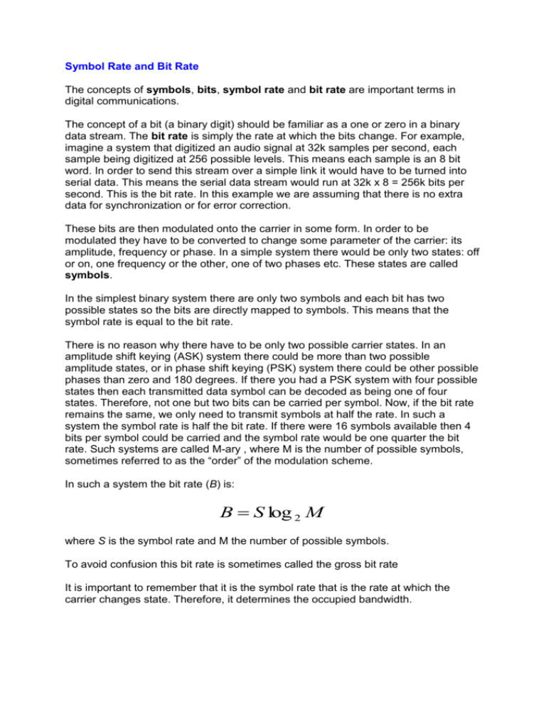
Symbol Rate and Bit Rate The concepts of symbols, bits, symbol rate and bit rate are important terms in digital communications. The concept of a bit (a binary digit) should be familiar as a one or zero in a binary data stream. The bit rate is simply the rate at which the bits change. For example, imagine a system that digitized an audio signal at 32k samples per second, each sample being digitized at 256 possible levels. This means each sample is an 8 bit word. In order to send this stream over a simple link it would have to be turned into serial data. This means the serial data stream would run at 32k x 8 = 256k bits per second. This is the bit rate. In this example we are assuming that there is no extra data for synchronization or for error correction. These bits are then modulated onto the carrier in some form. In order to be modulated they have to be converted to change some parameter of the carrier: its amplitude, frequency or phase. In a simple system there would be only two states: off or on, one frequency or the other, one of two phases etc. These states are called symbols. In the simplest binary system there are only two symbols and each bit has two possible states so the bits are directly mapped to symbols. This means that the symbol rate is equal to the bit rate. There is no reason why there have to be only two possible carrier states. In an amplitude shift keying (ASK) system there could be more than two possible amplitude states, or in phase shift keying (PSK) system there could be other possible phases than zero and 180 degrees. If there you had a PSK system with four possible states then each transmitted data symbol can be decoded as being one of four states. Therefore, not one but two bits can be carried per symbol. Now, if the bit rate remains the same, we only need to transmit symbols at half the rate. In such a system the symbol rate is half the bit rate. If there were 16 symbols available then 4 bits per symbol could be carried and the symbol rate would be one quarter the bit rate. Such systems are called M-ary , where M is the number of possible symbols, sometimes referred to as the “order” of the modulation scheme. In such a system the bit rate (B) is: B S log 2 M where S is the symbol rate and M the number of possible symbols. To avoid confusion this bit rate is sometimes called the gross bit rate It is important to remember that it is the symbol rate that is the rate at which the carrier changes state. Therefore, it determines the occupied bandwidth. It is clear that for a given bandwidth, the higher the order of the modulation scheme the less bandwidth is used. However there is a penalty to be paid. When demodulated, the higher the order of the scheme the more likely there are to be errors. This is obvious because, for example, it is clearly easier to detect the difference between 0 and 180 degrees than zero, 90, 180, and 270. There is another compromise to be made if error correcting data is added in that, although adding extra data reduces the number of errors, the bit rate has to rise, with a consequential increase in occupied bandwidth and received noise. In order to calculate the amount of useful data that can be transmitted through a digital system, first find the symbol rate. Then calculate the bit rate by using the number of bits per symbol. The useful data, sometimes referred to as the ‘payload’, can then be calculated by subtracting the extra data added for error correction, data identification and synchronisation. In a multiplexed system more than one data stream may be present and you may have to find out what proportion of the data stream is allocated to a particular set of data. In very complex systems this proportion may not even be constant!
