thk_lab4
advertisement
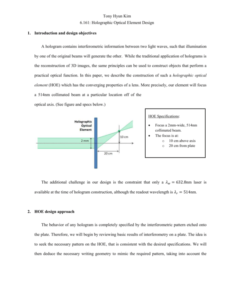
Tony Hyun Kim 6.161: Holographic Optical Element Design 1. Introduction and design objectives A hologram contains interferometric information between two light waves, such that illumination by one of the original beams will generate the other. While the traditional application of holograms is the reconstruction of 3D images, the same principles can be used to construct objects that perform a practical optical function. In this paper, we describe the construction of such a holographic optical element (HOE) which has the converging properties of a lens. More precisely, our element will focus a 514nm collimated beam at a particular location off of the optical axis. (See figure and specs below.) HOE Specifications: Focus a 2mm-wide, 514nm collimated beam. The focus is at: o 10 cm above axis o 20 cm from plate The additional challenge in our design is the constraint that only a 𝜆𝑤 = 632.8nm laser is available at the time of hologram construction, although the readout wavelength is 𝜆𝑟 = 514nm. 2. HOE design approach The behavior of any hologram is completely specified by the interferometric pattern etched onto the plate. Therefore, we will begin by reviewing basic results of interferometry on a plate. The idea is to seek the necessary pattern on the HOE, that is consistent with the desired specifications. We will then deduce the necessary writing geometry to mimic the required pattern, taking into account the Tony Hyun Kim 6.161: Holographic Optical Element Design difference in the write and read beams. Note that the final step would not be necessary if not for the additional complication of 𝜆𝑤 ≠ 𝜆𝑟 . 3. Review of interferometry Consider the interference of two plane waves in a recording material. In the diagram to the right, 𝜑 denotes the angle between the optical axis and the “halfway”-axis of the two interfering beams; 𝜃 is the angle between the two beams. The resulting interference pattern is completely characterized by the fringe separation Λ and the fringe direction. 𝜃 It is easy to showi that the fringe separation in the pattern is given by: Λ = λ⁄[2 sin (2 )]. It is also clear that the fringe direction makes angle 𝜙 with respect to the main axis. These results will allow us to find a scheme for preserving the interferometric pattern on the hologram (and hence its function) despite our read/write wavelength mismatch. 4. Conversion of the HOE specifications into a particular interference pattern Suppose that we had the readout laser 𝜆𝑟 = 514nm at the time of the write. The desired HOE could then be generated by the straightforward writing geometry shown below.ii We wish to characterize the interference pattern that is written onto the hologram. For simplicity, we analyze only the edges of the reference beam (points A and B in the diagram), and use the plane wave approximation. Using the formulas of the previous section, we find the following results. Tony Hyun Kim 6.161: Holographic Optical Element Design 5. Required writing geometry for 𝝀𝒘 = 𝟔𝟑𝟐. 𝟖nm The remaining task is to deduce the necessary writing geometry for 𝜆𝑤 ≠ 𝜆𝑟 that will preserve the interference pattern. The orientation of the halfway-axis 𝜙 should obviously remain invariant, in order to preserve fringe directions. However, we must modify the angle between the two beams, as to compensate for the change in wavelength. Again, we use the equations of interference to find: Since the separation of points A and B is known, the angular data can be used to find the new writing geometry. In particular, note that the new reference beam is slightly divergent, and the focus of the object beam has been relocated. We illustrate the final writing geometry below. Tony Hyun Kim 6.161: Holographic Optical Element Design 6. Conclusions We have described the construction of a holographic optical element (HOE) that can focus a 2mm-wide, 514nm collimated beam to an off-axis focal point. The design was complicated by the need to generate the hologram with a write laser whose wavelength differs from that of the readout laser. However, our design recognized that the response of any hologram is completely specified by the interferometric pattern imprinted on the plate. Therefore, we were able to prescribe a modified writing geometry using the 632.8nm laser, which would preserve the pattern of the desired HOE, and therefore also the function. i C. Warde. “Class notes for MOL – Coherence and Interference.” Pg 9-11. ii C. Warde. “Class notes for MOL – Principles of Holography.” Pg 6-9.
