Bimaterial Actuators
advertisement
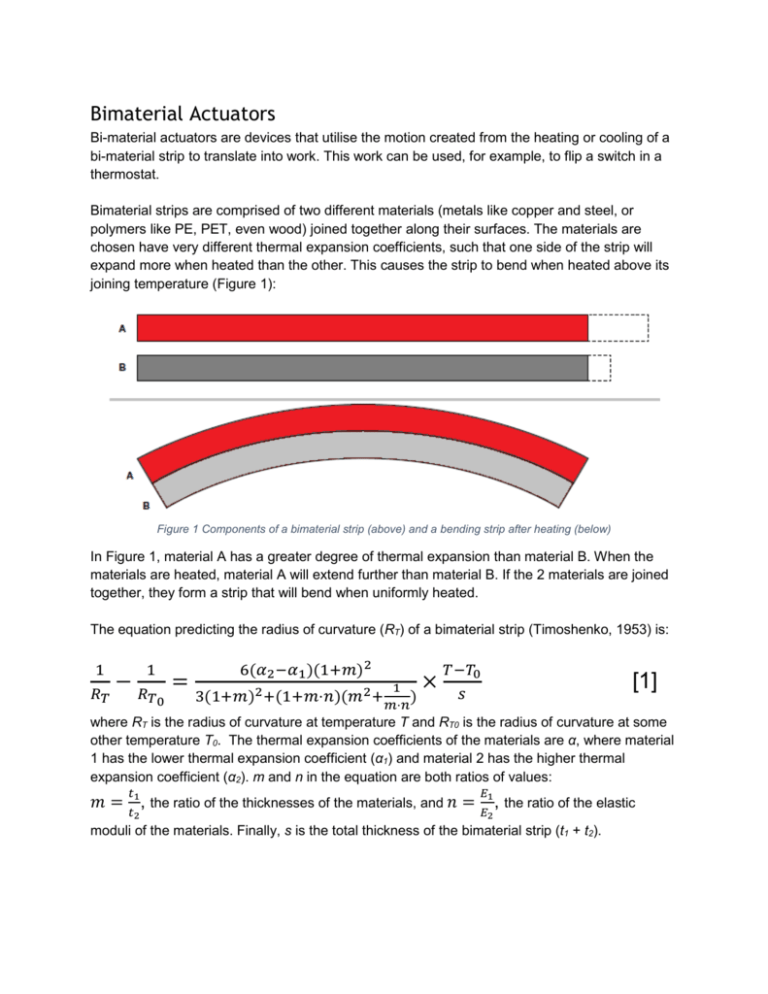
Bimaterial Actuators Bi-material actuators are devices that utilise the motion created from the heating or cooling of a bi-material strip to translate into work. This work can be used, for example, to flip a switch in a thermostat. Bimaterial strips are comprised of two different materials (metals like copper and steel, or polymers like PE, PET, even wood) joined together along their surfaces. The materials are chosen have very different thermal expansion coefficients, such that one side of the strip will expand more when heated than the other. This causes the strip to bend when heated above its joining temperature (Figure 1): Figure 1 Components of a bimaterial strip (above) and a bending strip after heating (below) In Figure 1, material A has a greater degree of thermal expansion than material B. When the materials are heated, material A will extend further than material B. If the 2 materials are joined together, they form a strip that will bend when uniformly heated. The equation predicting the radius of curvature (RT) of a bimaterial strip (Timoshenko, 1953) is: 1 1 6(𝛼2 −𝛼1 )(1+𝑚)2 𝑇−𝑇0 1 𝑅𝑇 𝑠 3(1+𝑚)2 +(1+𝑚⋅𝑛)(𝑚2 + ) 𝑇0 𝑚⋅𝑛 where RT is the radius of curvature at temperature T and RT0 is the radius of curvature at some other temperature T0. The thermal expansion coefficients of the materials are α, where material 1 has the lower thermal expansion coefficient (α1) and material 2 has the higher thermal expansion coefficient (α2). m and n in the equation are both ratios of values: −𝑅 = × [1] 𝑡 𝐸1 𝑡2 𝐸2 𝑚 = 1, the ratio of the thicknesses of the materials, and 𝑛 = , the ratio of the elastic moduli of the materials. Finally, s is the total thickness of the bimaterial strip (t1 + t2). It is clear from the equation that the change in radius of curvature is directly proportional to the change in temperature and difference in thermal expansion coefficients. Additionally, a smaller thickness also increases the bending of the bimaterial. The relationship between the ratios m and n must be optimised to maximise the radius of curvature. The ideal relationship between the two ratios can be found to be: 𝑚= √𝑛 𝑛 Comparing this relation with the equation for stiffness (from elastic modulus and thickness), we find that for this relationship to be true the two material layers must have the same stiffness. This tells us that the degree of bending increases as the difference in stiffness between the two materials decreases. Typically, the first term in the equation can be calculated for a bi-material with known thickness and modulus ratios into a value known as specific curvature or flexivity. Specific curvature is the figure of merit for the bendability of bi-materials. This value is represented in equations by k. Additionally, if at the reference temperature (T0) the strip is flat (i.e. RT0 is ∞) then equation 1 simplifies to: 1 𝑅𝑇 =𝑘 𝑇−𝑇0 𝑠 [2] Aside from the properties derived from equation [1], the materials used in a bimaterial strip must be able to handle the conditions of manufacturing and operation. Both material should have strain capacity such that it does not fail at the maximum strains expected during bending. Additionally, it can be seen in equation [2] that decreasing the thickness decreases the radius of bending. To maximise bending for a given temperature change the strip must be as thin as possible. The material must then be strong to be formed (rolled or extruded) to the desired thickness. Equation [1] may be manipulated to make the equations easier to implement for our application. The following equations are all derived in part from equation [1]. Figure 2 Illustration of bimaterial strip in deflection Deflection (unhindered) of a uniformly heated bimaterial strip follows equation [3], 𝑨= 𝒂𝑳𝟐 𝟒𝒔 ⋅ 𝜟𝑻 [3] where A is the deflection (shown in Figure 2), L is the length of strip, and ΔT is the change in temperature. Instead of using k, in this equation a is the specific deflection. Specific deflection is a term that measures a material’s change in longitudinal curvature per unit temperature change. The term is a variation of specific curvature, where specific deflection is simply half the value of specific curvature. To calculate the force, P, exerted by a deflecting bimaterial the average Young’s modulus, E, and width, B, of the bimaterial strip must be included. Force of a suppressed deflecting heated bimaterial strip thus follows equation [4], 𝑃= 𝑎𝐸𝐵𝑠 2 𝐿 ⋅ 𝛥𝑻 [4] Common bimaterial strips are usually made from steel and copper or steel and brass. These strips are found often in thermometers or switches (Betts, 2006). Less common polymer bimaterial strips use different thickness films of PET and PE (Blonder, 2013). More expensive bimaterial strips use alloys of iron, nickel, manganese and/or chrome of varying compositions as the active component with Invar (or a similar alloy) usually serving as the passive component (Webster, 1999). These higher-end strips use materials with a greater Δα and more similar moduli to improve performance. The two components may be joined in any way that holds the materials together along their length. This includes rivets, welding (Capgo Pty Ltd., 2010), roll-joining (cold bonding) (Kanthal AB, 2008), or adhesives (Blonder, 2013). For our application we require the bimaterial actuators pull the sides of our frame to a 90° bend. The required angle of curvature can then be calculated to be approximately 160° (see appendix). θ r The angle of curvature, θ, and radius of curvature, r, can now be used to calculate the required deflection following this equation: 𝐷𝑒𝑓𝑙𝑒𝑐𝑡𝑖𝑜𝑛 = 𝐴 = 𝑟 𝜃 2 𝑠𝑖𝑛 2 − 𝑟 2 𝑡𝑎𝑛 𝜃 2 [5] This deflection can then be used in equation [3] to determine what specific deflection will be required. It can be seen in equation [3] that the deflection amount also increases with increasing length and decreasing thickness. In our research, commercially available bimetals have a lower thickness limit of approximately 80μm and specific deflections ranging from 9.8x10⁻⁶/K to 20.8x10⁻⁶/K (IMPHY S.A.). Calculated specific deflections of other bimaterials (including bi-polymers), however, can potentially exceed 120x10-6/K. References Betts, J. (2006). John Harrison (1693–1776) and Lt. Cdr Rupert T. Gould R.N. (1890–1948). Greenwich: National Maritime Museum / Royal Observatory. Blonder, G. (2013, September 30). C)) Motion Bimorph Material. (J. Leung, Interviewer) Capgo Pty Ltd. (2010). Bimetalic strips. Retrieved from Capgo: http://www.capgo.com/Resources/Temperature/BiMet/BiMetallic.html IMPHY S.A. (n.d.). Thermostatic Bimetals. Paris. Kanthal AB. (2008). Thermostatic Bimetal Handbook. Hallstahammar: Kanlthal AB. Timoshenko, S. (1953). The Collected Papers. New York: McGraw-Hill. Webster, J. (1999). The Measurement, Instrumentation, and Sensors Handbook. Boca Raton: CRC Press LLC. Appendix We require a hinge that will actuate to sides of a frame about 90°. r θ L To achieve this, the bimaterial needs to have a certain angle of curvature, θ. As we know the length of the arc to be the length of the bimaterial strip we can calculate the chord length (straight line between the ends of the arc) with respect to the angle of curvature and radius of curvature, r: 𝜃 𝐶ℎ𝑜𝑟𝑑 𝑙𝑒𝑛𝑔𝑡ℎ = 𝑟 × 2𝑠𝑖𝑛( ) [6] 2 The radius of curvature is calculated using the arc length (bimaterial length) and the angle of curvature: 𝑅𝑎𝑑𝑖𝑢𝑠 𝑜𝑓 𝑐𝑢𝑟𝑣𝑎𝑡𝑢𝑟𝑒 = 𝑟 = 𝐿 𝜃 ) 360 (2×𝜋× [7] Because the chord length must also be such that the sides of the blinds reach 90°, the chord length can also be calculated with respect to the arc length (bimaterial length) using the Pythagorean theorem: 𝐶ℎ𝑜𝑟𝑑 𝑙𝑒𝑛𝑔𝑡ℎ = √2 × (½ 𝐿)2 [8] When these equations are combined the arc length cancels out and we are left with the angle of curvature which is 159.46°.
