et_chamonix_2014_v2 - Indico
advertisement
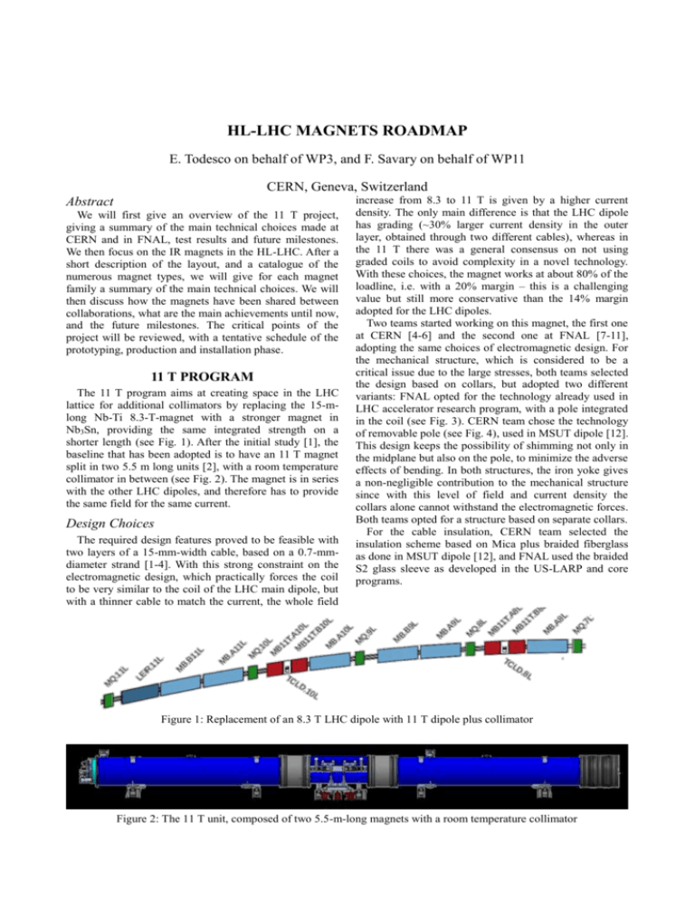
HL-LHC MAGNETS ROADMAP E. Todesco on behalf of WP3, and F. Savary on behalf of WP11 CERN, Geneva, Switzerland Abstract We will first give an overview of the 11 T project, giving a summary of the main technical choices made at CERN and in FNAL, test results and future milestones. We then focus on the IR magnets in the HL-LHC. After a short description of the layout, and a catalogue of the numerous magnet types, we will give for each magnet family a summary of the main technical choices. We will then discuss how the magnets have been shared between collaborations, what are the main achievements until now, and the future milestones. The critical points of the project will be reviewed, with a tentative schedule of the prototyping, production and installation phase. 11 T PROGRAM The 11 T program aims at creating space in the LHC lattice for additional collimators by replacing the 15-mlong Nb-Ti 8.3-T-magnet with a stronger magnet in Nb3Sn, providing the same integrated strength on a shorter length (see Fig. 1). After the initial study [1], the baseline that has been adopted is to have an 11 T magnet split in two 5.5 m long units [2], with a room temperature collimator in between (see Fig. 2). The magnet is in series with the other LHC dipoles, and therefore has to provide the same field for the same current. Design Choices The required design features proved to be feasible with two layers of a 15-mm-width cable, based on a 0.7-mmdiameter strand [1-4]. With this strong constraint on the electromagnetic design, which practically forces the coil to be very similar to the coil of the LHC main dipole, but with a thinner cable to match the current, the whole field increase from 8.3 to 11 T is given by a higher current density. The only main difference is that the LHC dipole has grading (~30% larger current density in the outer layer, obtained through two different cables), whereas in the 11 T there was a general consensus on not using graded coils to avoid complexity in a novel technology. With these choices, the magnet works at about 80% of the loadline, i.e. with a 20% margin – this is a challenging value but still more conservative than the 14% margin adopted for the LHC dipoles. Two teams started working on this magnet, the first one at CERN [4-6] and the second one at FNAL [7-11], adopting the same choices of electromagnetic design. For the mechanical structure, which is considered to be a critical issue due to the large stresses, both teams selected the design based on collars, but adopted two different variants: FNAL opted for the technology already used in LHC accelerator research program, with a pole integrated in the coil (see Fig. 3). CERN team chose the technology of removable pole (see Fig. 4), used in MSUT dipole [12]. This design keeps the possibility of shimming not only in the midplane but also on the pole, to minimize the adverse effects of bending. In both structures, the iron yoke gives a non-negligible contribution to the mechanical structure since with this level of field and current density the collars alone cannot withstand the electromagnetic forces. Both teams opted for a structure based on separate collars. For the cable insulation, CERN team selected the insulation scheme based on Mica plus braided fiberglass as done in MSUT dipole [12], and FNAL used the braided S2 glass sleeve as developed in the US-LARP and core programs. Figure 1: Replacement of an 8.3 T LHC dipole with 11 T dipole plus collimator Figure 2: The 11 T unit, composed of two 5.5-m-long magnets with a room temperature collimator performance with adequate margin. On the other hand, longer training was observed in the full model, with a nominal current reached with several tens of quenches, and limited margin (see for instance Fig. 5 where the mirror and the full model built at FNAL are compared – nominal current is 11.8 kA); moreover, in some cases the magnet quenches after reaching at nominal current (so called “holding quenches”); in other cases, a significant detraining has been observed. These points need to be addressed to have magnets that can be installed in the LHC. Figure 3: FNAL Cross-section of the 11 T dipole. Figure 5: Training of the FNAL mirror, and of the first and second 1-m-long apertures. Nominal current is 11.8 kA Production Plans Figure 4: CERN Cross-section of the 11 T dipole. Required Units One 11 T unit is made of two 5.5-m-long dipoles with a room temperature collimator (see Fig. 3). In the second long shutdown [2], foreseen for 2018, two 11 T units are needed around the interaction point 2 (Alice) for ion collimation. In the third long shutdown [2], four units are needed around point 7, in the section used for cleaning. As an option [2], eight additional units could be installed around ATLAS and CMS (four units for each interaction point). Since one unit is made by two 5.5-m-long magnets, each one with 4 coils (double aperture dipole), this implies the construction of 16 coils for LS2 and 32 coils for LS3, with an option of 64 more coils, plus spares. Present Status During the past years, FNAL built an initial single aperture 2-m-long model [3], and two more 1-m-long models [9-11], that have been recently assembled in the first two-in-one Nb3Sn magnet ever made. Performances were showing encouraging results of the mirror, with nominal reached with ~10 quenches, and ~90% of short sample reached after training. This proves that manufactured strand, cable and coil can reach the required The FNAL contribution to the project is expected to end with the construction and test of a short two-in-one model. CERN continues the short model program, consisting of four single apertures and two double apertures, and is planning to build a long prototype in 2016. For the production of the series, no external collaboration is foreseen at the moment; due to the large quantity of coils and the temporal overlap with the Nb 3Sn inner triplet (see next section), it is probable that the production of the coil has to be done in the industry [13]. At the same time, the solutions needed for the cryostat bypass to house the room temperature collimator are being engineered and will be tested in the first magnet for IP2. MAGNETS FOR THE IR UPGRADE The new layout of the insertion regions aims at doubling the aperture of the present triplet to allow reducing the beam size by a factor two in the interaction point [14]. This gives a potential increase in peak luminosity of a factor four. Nb3Sn is the enabling technology since, thanks to the 50% higher gradient reachable in the same aperture, it allows to increase the aperture, still keeping the triplet compact, i.e. less than 10 m longer than in the LHC layout (see Fig. 6). The other magnets between the triplet and the matching section quadrupole have to be replaced, to match the aperture increase. They are all in Nb-Ti technology since their length is not critical for performance. Q2 Q3 DFB Q1 D1 D2 Q4 Q: 200 T/m MCBX: 3.3 T 1.5 T m D1: 1.8 T 26 T m 60 100 distance to IP (m) 120 D1 140 160 D2 80 100 distance to IP (m) 120 140 180 MCBYY MQYY Q4 MCBRB Q3 MCBXFB MCBXFB 40 80 MBRB Q2a Q2b Q1 20 60 MBXF 40 MCBXFA 20 160 180 Figure 6: Layout of the interaction region around ATLAS and CMS foreseen for 2024 (after long shutdown 3), compared to present layout Main Design Choices The main guidelines of the design were (i) to have the maximum performance, i.e. aiming at the largest possible aperture in the triplet using Nb3Sn [15], pushed at the maximum performance with a peak field in the coil of ~12 T; (ii) have the other main magnets in Nb-Ti technology [16-18] with peak fields of the order of 6 T; (iii) to have the full set of correctors required by beam dynamics, given the large values of beta function in the triplet region, which make the beam sensitive to any small imperfection in that region [19-20]. The complete list of parameters can be found in the preliminary design report and in the WP3 web site [14]. Here we briefly outline the main design choices. The triplet is made of four 150 mm aperture Nb 3Sn quadrupoles, with nominal gradient of 140 T/m at 80% of the loadline [15]. The four magnets (Q2 is split in two, as in the LHC, see Fig. 6) have lengths of 7 to 8 m. Recently, it has been decided to increase these lengths by ~3540 cm, thus allowing to reduce the operational gradient to 132.6 T/m, increasing the margin on the loadline from 20 to 25 %. The magnet deign (see Fig. 7) is a scale-up of the 120 mm aperture quadrupole HQ successfully developed by LARP [21]: (i) double layer coil, with four blocks, (ii) bladders and key structure allowing a very precise control of mechanical loading at room temperature, and (iii) an aluminium shell to support the electromagnetic forces. Figure 7: CERN Cross-section of the triplet QXF. The separation dipole is a 150-mm-aperture Nb-Ti dipole, with an operational field of 5.6 T at 75% of the loadline, and 6 m length. It is a single layer coil with thin collars (see Fig. 8) to maximize the quantity of iron, thus reducing saturation effect below the targets [16]. The mechanical structure relies on the iron to keep the electromagnetic forces (collars are too thin to have a selfstanding collar structure as in the LHC dipole). The recombination dipole is a Nb-Ti two-in-one 105mm-aperture magnet with 4.5 T operational field, working at 65% of the loadline. Here the limitation is the electromagnetic cross-talk between the apertures, imposing (i) a rectangular frame to reduce the saturation on b3 and (ii) no iron between the apertures, and left right asymmetric coils, as proposed in [22], to reduce the saturation effect on b2. A sketch of the design is given in Fig. 9. Note the elliptic iron yoke to reduce the fringe field and the saturation effects. Figure 10: Cross-section of the quadrupole Q4. Figure 8: Cross-section of the separation dipole D1. The two-in-one quadruple Q4 [18] is a Nb-Ti 90-mmaperture magnet with 115 T/m operational gradient, working at 80% of the loadline (see Fig. 10). The single aperture corrector magnets provide a considerable integrated field (2.5 and 4.5 T m). They are based on nested coils [19], giving 2.1 T maximum fields in horizontal and vertical plane (see Fig. 11). A two-layer coil in each plane, using a 4.5-mm-width Rutherford cable, provides the required field with a comfortable margin (~60% on the loadline). The mechanical structure relies on self-standing collars, with the external coil being collared on the internal one. An inner tube is needed to keep the electromagnetic forces from bending the coil towards the beam tube, when both coils are powered. The high order correctors are superferric magnets [20] with peak field of the order of 1.5 T, and length of ~10 cm, with the exception of the skew quadrupole (~85 cm) and the normal dodecapole (~45 cm). The coil is made with Nb-Ti wire, giving operational currents of the order of 100 A, and the iron is at 1.9 K (see Fig. 12 for the skew quadrupole). The two-in-one orbit correctors close to D2 and Q4 provide 4.5 T m, with a nominal field of 2.8 T. As in D2, the main issue in the design of this magnet is the magnetic cross-talk between the apertures, given the large aperture (105 mm) and the fixed LHC interbeam distance of 192 mm (see Fig. 13). Figure 9: Cross-section of the recombination dipole D2. Figure 11: Cross-section of the nested orbit corrector. Status and Production Plan: Main Magnets Figure 12: Cross-section of the skew quadrupole. The main magnets are characterized by similar features: (i) a very small series (4 units plus two spares), (ii) same Nb-Ti technology (iii) lengths in the 4 to 8 m range. The separation dipole activity is steered by KEK, where the conceptual design started already in 2013 [16]. The test of the first short model is foreseen for 2015, and a second one to be manufactured in 2016. The series could be a in-kind contribution of Japan, and could be realized in the Japanese industry in the period 2019-2021. The recombination dipole design study started in early 2014 in INFN Genova [17]. The team rapidly converged on a conceptual design during 2014, and now the engineering of a short model is in progress. The plan is to have a short model manufactured by industry in 2016, with a test at the end of 2016 or beginning of 2017. The series should also be built in the industry, in the period 2019-2021. The activities related to the matching section quadrupole Q4 started in CEA-Saclay in 2012 [18]. Conceptual design has been completed in 2013, and engineering started in 2014. First winding test have been carried out in early 2015 in CEA. The plan is to have a short model manufactured during 2016, and a test in single and double aperture configuration in 2017. Also in this case production should be carried out in the industry in the period 2019-2021. Status and Production Plan: Correctors Figure 13: Cross-section of the two-in-one orbit corrector. Status and Production Plan: Triplet The inner triplet will be shared between CERN and USHiLumi, with the Europeans building the Q2 (eight units plus two spares), and the Americans the Q1 and the Q3 (eight units plus two spares). The collaboration has chosen the same design to maximize the synergies. The added value is particularly evident in the short model program, where coils built at CERN and in the US can be exchanged and assembled in the same magnet. The first short model will be assembled and tested in 2015, and four more models are foreseen. At the prototype stage, the two collaborations will have magnets with different lengths. The US collaboration also decided to have a split magnet, with a minimal loss of performance. Two prototypes are foreseen at CERN, and one and a half (three 4-m-long magnets) in the US, to be tested in 2016-2018. Production is foreseen for the period 2019-2023. Schedule is tight, allowing a very limited possibility of feedback. The orbit corrector magnets are designed by CIEMAT; conceptual design of the magnet was completed in 2015 [19], with sill some decisions to be taken on the cable insulations scheme and on the option of impregnating the coil. First winding tests will be carried out in 2015, and a short model will be built in collaboration between CIEMAT (winding) and CERN (collaring), and tested in 2016. The series is foreseen to be built in the industry during the years 2018-2020. The nonlinear corrector prototypes are a contribution of INFN-LASA [20]. The Italian laboratory carried out the conceptual design and has made the first winding tests in early 2015. Prototypes of each of the five different types of magnets (from skew quadrupole to dodecapole) are planned to be built and tested in LASA in the period 2015-2017. Production could start right after in 20182019 in the industry. The double aperture orbit corrector will be developed at CERN in 2017. Due to the larger number of coils (64 plus spares), also this production goes beyond a laboratory optimal charge, and it is planned for the industry. A summary of the first tentative sharing between CERN, collaborations and industry of the different phases of the model, prototyping and production is given in Fig 14. Model Prototype Series Q1/Q3 MQXFA Coil US-HILUMI Assembly US-HILUMI Cold mass V test US-HILUMI Coil US-HILUMI Assembly US-HILUMI Cold mass US-HILUMI V test US-HILUMI Cryostat CERN CMI H test US-HILUMI Coil US-HILUMI Assembly US-HILUMI V test US-HILUMI Cold mass US-HILUMI Cryostat CERN CMI H test CERN TF Q2 MQXFB CERN MDT CERN MDT CERN TF CERN LMF CERN LMF CERN LMF CERN CMI CERN TF CERN LMF CERN LMF orbit MCBXFB orbit MCBXFA HO correctors CIEMAT CIEMAT Industry-1 Industry-1 CERN TF CERN TF INFN LASA INFN LASA CERN LMF INFN LASA CERN CMI CERN TF Industry-2 Industry-2 INFN LASA CERN LMF CERN CMI CERN TF Industry-1 Industry-1 CERN TF Industry-1 Industry-1 CERN TF CERN LMF CERN CMI CERN TF D1 MBXF KEK KEK KEK KEK Industry-3 Industry-3 Industry-3 KEK KEK CERN TF Industry-3 Industry-3 KEK Industry-3 KEK CERN TF D2 MBRB Industry-4 Industry-4 INFN LASA Industry-4 Industry-4 CERN LMF CERN CMI CERN TF Industry-4 Industry-4 CERN LMF CERN CMI CERN TF Q4 D2 Q4 correctors MQYY MCBRB/YY CEA CERN MDT CEA Industry-5 Industry-5 CERN LMF CEA CERN CMI CERN TF Industry-5 Industry-5 CEA CEA CERN CMI CERN TF CERN MDT CERN MDT CERN TF Industry-6 Industry-6 CERN TF Figure 14: First plan for the sharing of the IR magnets for HL-LHC. CONCLUSIONS We presented here the roadmap for the new magnets of the HL-LHC project. For the 11 T results of few short models built at FNAL and at CERN are already available. The construction of a first 5.5-m-long magnet will be an important milestone for the project. The plan foresees the installation of 2 units within the tight deadline of 2018, and four units in 2023. For the IR magnets, to be installed in 2023, nearly 100 units have to be built. The layout and the conceptual design of all magnets have been completed. Fine tuning of the layout is in progress, taking into account of minor changes of margins and lengths, and a better definition of the interfaces between magnets. The sharing of the magnets design and/or construction between five international collaborations (US HiLumi, CIEMAT, CEA, INFN, KEK) is taking shape and a first baseline is available, summarized in Fig. 14. The test of the first three magnets of HL LHC IR regions (triplet, separation dipole and sextupole corrector) is foreseen for 2015. REFERENCES [1] G. De Rijk, A. Milanese, E. Todesco, “11 Tesla Nb3Sn dipoles for phase II collimation in the Large Hadron Collider”, CERN SLHC Project Note 19 (2010). [2] M. Karppinen, D. Ramos, F. Savary, S. Zlobin, “11 T dipole for the dispersion suppressor collimators, in “Preliminary design report of HL LHC”, CERNACC-2014-103 (2014) 227-233. [3] A. Zlobin, et al., “Design and fabrication of a singleaperture 11 T Nb3Sn dipole model for LHC upgrades”, IEEE Trans. Appl. Supercond. 22 (2012) 4001705. [4] M. Karppinen, et al., “Design of 11 T twin-aperture Nb3Sn dipole demonstrator magnet for LHC upgrades”, IEEE Trans. Appl. Supercond. 22 (2012) 4901504. [5] F. Savary, et al., “Status of the 11 T Nb3Sn dipole project for the LHC”, IEEE Trans. Appl. Supercond. 25 (2015) 4003205. [6] F. Savary, et al., “Design, assembly and test of the CERN 2-m-long 11 T dipole in single coil configuration”, IEEE Trans. Appl. Supercond. 25 (2015) 4004105. [7] A. Zlobin, et al., “Development and test of a singleaperture 11 T Nb3Sn demonstrator dipole for LHC upgrades”, IEEE Trans. Appl. Supercond. 23 (2013) 4000904. [8] N. Andreev, et al., “Field quality measurements in a single aperture 11 T Nb3Sn demonstrator dipole for LHC upgrades”, IEEE Trans. Appl. Supercond. 23 (2013) 4001804. [9] A. Zlobin, et al., “Quench performance of a 1-m-long single-aperture 11 T Nb3Sn dipole model for LHC upgrades”, IEEE Trans. Appl. Supercond. 24 (2014) 4000305. [10] G. Chlachidze, et al., “Field quality study of a 1-mlong single-aperture 11-T Nb3Sn dipole model for LHC upgrades”, IEEE Trans. Appl. Supercond. 24 (2014). [11] A. Zlobin, et al., “11 T twin-aperture Nb3Sn dipole development for LHC upgrades”, IEEE Trans. Appl. Supercond. 25 (2015) 4002209. [12] H. ten Kate, et al., “An experimental 11.5 T Nb3Sn LC type of dipole magnet, IEEE Trans. Magn. 30 (1994) 2320-2323. [13] L. Bottura, talk at the cost and schedule review, March 2015. [14] E. Todesco, et al., “Insertion Magnets”, in “Preliminary design report of HL LHC”, CERNACC-2014-103 (2014) 87-106 and updated parameters on www.cern.ch/hilumi/wp3 [15] P. Ferracin, et al., “Magnet design of the 150 mm aperture low-beta quadrupole for the high luminosity LHC”, IEEE Trans. Appl. Supercond. 24 (2014) 4002306. [16] T. Nakamoto, et al., “Model magnet development of D1 beam separation dipole for the HL-LHC upgrade”, IEEE Trans. Appl. Supercond. 25 (2015) 4000505. [17] P. Fabbricatore, et al., “The design of superconducting separation dipoles D2 for the high luminosity upgrade of LHC”, IEEE Trans. Appl. Supercond. 26 (2016) to be published. [18] J. M. Rifflet, et al., “A Nb-Ti 90 mm double aperture quadrupole for the high luminosity LHC upgrade”, IEEE Trans. Appl. Supercond. 25 (2015) 4001905. [19] F. Toral, et al., “Magnetic and mechanical design of the nested orbit correctors for HL-LHC”, IEEE Trans. Appl. Supercond. 26 (2016) to be published. [20] G. Volpini, et al., “Nb-Ti superferric corrector magnets for the LHC luminosity upgrade”, IEEE Trans. Appl. Supercond. 25 (2015) 4002605. [21] H. Felice, et al., “Design of HQ, a high field large bore Nb3Sn quadrupole magnet for LARP”, IEEE Trans. Appl. Supercond. 19 (2009) 1235-39. [22] V. Kashikin, et al., “Design study of 2-in-1 large aperture IR dipole (D2) for the LHC luminosity upgrade”, Particle Accelerator Conference. (2007) 464-6.
