Measurment systems, control systems
advertisement
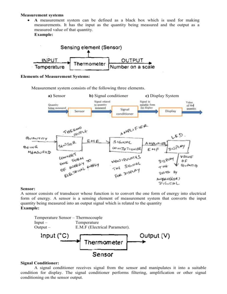
Measurement systems A measurement system can be defined as a black box which is used for making measurements. It has the input as the quantity being measured and the output as a measured value of that quantity. Example: Elements of Measurement Systems: Measurement system consists of the following three elements. a) Sensor b) Signal conditioner c) Display System Sensor: A sensor consists of transducer whose function is to convert the one form of energy into electrical form of energy. A sensor is a sensing element of measurement system that converts the input quantity being measured into an output signal which is related to the quantity Example: Temperature Sensor – Thermocouple Input – Temperature Output – E.M.F (Electrical Parameter). Signal Conditioner: A signal conditioner receives signal from the sensor and manipulates it into a suitable condition for display. The signal conditioner performs filtering, amplification or other signal conditioning on the sensor output. Example: Temperature measurement– Single Conditioner function (Amplifier) Input - Small E.M.F value (From sensor) Output – Big E.M.F Value (Amplified). Display System: A display system displays the data (output) from the signal conditioner by analog or digital. A digital system is a temporary store such as recorder. Example: Display movement Input Output – L.E.D (or) Number on scale by – Conditioned Signal (from signal conditioner) – Value of the quantity (Temperature) pointer Temperature Measurement System: Control systems A control system can be thought of as a system which can be used to: 1. Control some variable to some particular value, e.g. a central heating system where the temperature is controlled to a particular value. 2. Control the sequence of events e.g. a washing machine where when the dials are set to say “white” and the machine is then controlled to a particular washing cycle, i.e. sequence of events, appropriate to that type of clothing. 3. Control whether an event occur or not e.g. a safety lock on a machine where it cannot be operated until a guard is in position. Feedback: A feedback loop is a common and powerful tool when designing a control system. Feedback loops take the system output into consideration, which enables the system to adjust its performance to meet a desired output response. When talking about control systems it is important to keep in mind that engineers typically are given existing systems such as actuators, sensors, motors, and other devices with set parameters, and are asked to adjust the performance of those systems. In many cases, it may not be possible to open the system (the "plant") and adjust it from the inside: modifications need to be made external to the system to force the system response to act as desired. This is performed by adding controllers, compensators, and feedback structures to the system. The figure shows a simple feedback system. Open loop control system: An open-loop control system utilizes a controller or control actuator to obtain the desired response, as shown in Figure. An open-loop system is a system without feedback. An open-loop control system utilizes an actuating device to control the process directly without using feedback. Closed loop: In contrast to an open-loop control system, a closed-loop control system utilizes an additional measure of the actual output to compare the actual output with the desired output response. The measure of the output is called the feedback signal. A simple closed-loop feedback control system is shown in Figure A feedback control system is a control system that tends to maintain a prescribed relationship of one system variable to another by comparing functions of these variables and using the difference as a means of control. A closed-loop control system uses a measurement of the output and feedback of this signal to compare it with the desired output (reference or command). Elements of Closed Loop System: • Comparison Unit • Control Unit • Correction Unit • Process Unit • Measurement Device Comparison Unit This element compare the required or reference value of the variable condition being controlled with the measured value and produces error signal Error Signal = Ref Value – Measured Value Control Unit: Decide corrective action to be taken against error signal received by it Eg: A signal to operate switch on/off, valve open/close Correction Unit: It is an actuator that produces change in the process to correct or change the controlled condition Process Unit: The process is what is being controlled. Eg: Temperature of room Measurement Unit: Produces signal related to the variable condition of the process being controlled. Eg; Thermocouple System of controlling water level in tank: Shaft Speed Control: MICROCONTROLLER BASED CONTROLLERS Sequential Controllers: • It is used to control the process that are strictly ordered in a time or sequence DOMESTIC WASHING MACHINE: Pre Wash Cycle: • Pre-wash cycle may involve the following sequence of operations. • Opening of valve to fill the drum when a current is supplied • Microprocessor is used to operate the switch for opening & closing the valve. • Closing the valve after receiving the signal from a sensor when the required level of water is filled in the washing drum. • Stopping the flow of water after the current is switched off by the microprocessor. • Switch on the motor to rotate for stipulated time. • Initiates the operation of pump to empty the water from the drum. • Pre-wash cycle involves washing the clothes in the drum by cold water. Main Wash Cycle: • Main wash cycle involves washing the clothes in the drum by hot water and the sequence of operations in main wash is as follows: • Cold water is supplied after the Pre-wash cycle is completed. • Current is supplied in large amount to switch on the heater for heating the cold water. • Temperature sensor switches off the current after the water is heated to required temperature. • Microprocessor or cam switch ON the motor to rotate the drum • Microprocessor or cam switches on the current to a discharge pump to empty the drum. Rinse Cycle: • Rinse cycle involves washing out the clothes with cold water a number of times and the sequence of operations in a Rinse cycle are as follows: • Opening of valve to allow cold water into the drum when the microprocessor are given signals to supply current after the main wash cycle is completed. • Switches off the supply current by the signals from microprocessor • Operation of motor to rotate the drum • Operation of pump to empty the drum and respect this sequence a number of times. Spinning Cycle: • Spinning cycle involves removing of water from the clothes and the sequence of operations is • Switching on the drum motor to rotate it at a higher speed than a rinsing cycle.
