Problem Sheet 8
advertisement
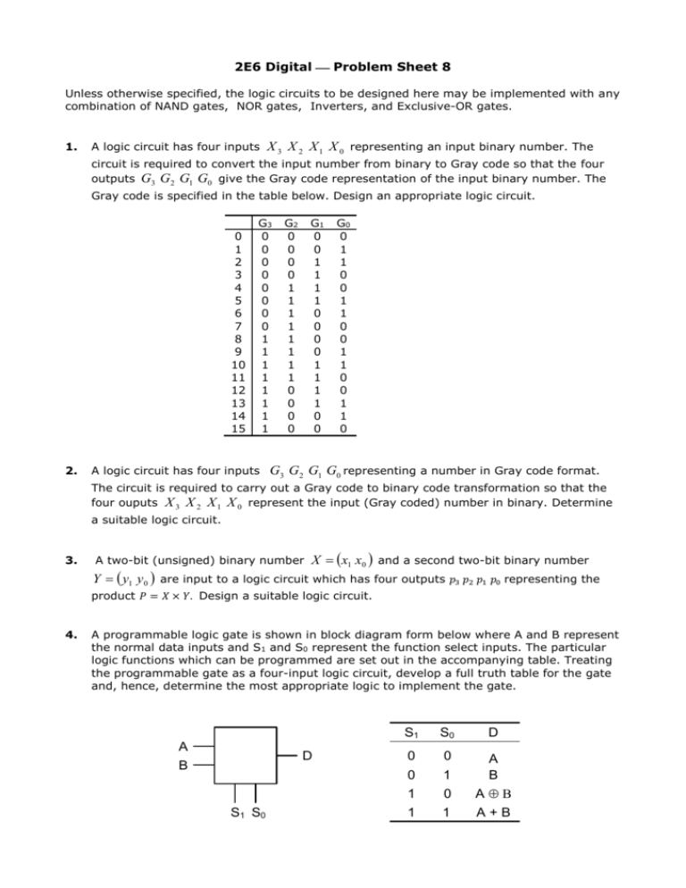
2E6 Digital Problem Sheet 8 Unless otherwise specified, the logic circuits to be designed here may be implemented with any combination of NAND gates, NOR gates, Inverters, and Exclusive-OR gates. 1. A logic circuit has four inputs X 3 X 2 X 1 X 0 representing an input binary number. The circuit is required to convert the input number from binary to Gray code so that the four outputs G3 G2 G1 G0 give the Gray code representation of the input binary number. The Gray code is specified in the table below. Design an appropriate logic circuit. 0 1 2 3 4 5 6 7 8 9 10 11 12 13 14 15 2. G3 0 0 0 0 0 0 0 0 1 1 1 1 1 1 1 1 A logic circuit has four inputs G2 0 0 0 0 1 1 1 1 1 1 1 1 0 0 0 0 G1 0 0 1 1 1 1 0 0 0 0 1 1 1 1 0 0 G0 0 1 1 0 0 1 1 0 0 1 1 0 0 1 1 0 G3 G2 G1 G0 representing a number in Gray code format. The circuit is required to carry out a Gray code to binary code transformation so that the four ouputs X 3 X 2 X 1 X 0 represent the input (Gray coded) number in binary. Determine a suitable logic circuit. 3. A two-bit (unsigned) binary number X x1 x0 and a second two-bit binary number Y y1 y 0 are input to a logic circuit which has four outputs 𝑝3 𝑝2 𝑝1 𝑝0 representing the product 𝑃 = 𝑋 × 𝑌. Design a suitable logic circuit. 4. A programmable logic gate is shown in block diagram form below where A and B represent the normal data inputs and S1 and S0 represent the function select inputs. The particular logic functions which can be programmed are set out in the accompanying table. Treating the programmable gate as a four-input logic circuit, develop a full truth table for the gate and, hence, determine the most appropriate logic to implement the gate. A B D S1 S0 S1 S0 D 0 0 1 1 0 1 0 1 A B AÅB A+B
