6_2_Oscilloscope-Han..
advertisement

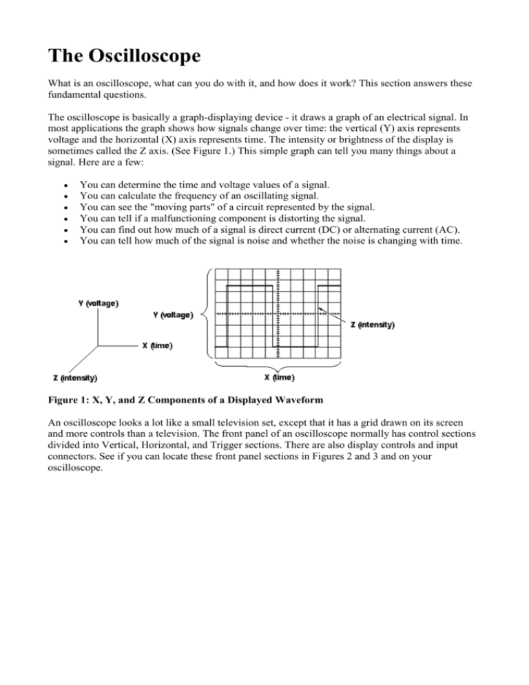
The Oscilloscope What is an oscilloscope, what can you do with it, and how does it work? This section answers these fundamental questions. The oscilloscope is basically a graph-displaying device - it draws a graph of an electrical signal. In most applications the graph shows how signals change over time: the vertical (Y) axis represents voltage and the horizontal (X) axis represents time. The intensity or brightness of the display is sometimes called the Z axis. (See Figure 1.) This simple graph can tell you many things about a signal. Here are a few: You can determine the time and voltage values of a signal. You can calculate the frequency of an oscillating signal. You can see the "moving parts" of a circuit represented by the signal. You can tell if a malfunctioning component is distorting the signal. You can find out how much of a signal is direct current (DC) or alternating current (AC). You can tell how much of the signal is noise and whether the noise is changing with time. Figure 1: X, Y, and Z Components of a Displayed Waveform An oscilloscope looks a lot like a small television set, except that it has a grid drawn on its screen and more controls than a television. The front panel of an oscilloscope normally has control sections divided into Vertical, Horizontal, and Trigger sections. There are also display controls and input connectors. See if you can locate these front panel sections in Figures 2 and 3 and on your oscilloscope. Figure 2: The TAS 465 Analog Oscilloscope Front Panel Figure 3: The TDS 320 Digital Oscilloscope Front Panel What Can You Do With It? Oscilloscopes are used by everyone from television repair technicians to physicists. They are indispensable for anyone designing or repairing electronic equipment. The usefulness of an oscilloscope is not limited to the world of electronics. With the proper transducer, an oscilloscope can measure all kinds of phenomena. A transducer is a device that creates an electrical signal in response to physical stimuli, such as sound, mechanical stress, pressure, light, or heat. For example, a microphone is a transducer. An automotive engineer uses an oscilloscope to measure engine vibrations. A medical researcher uses an oscilloscope to measure brain waves. The possibilities are endless. Figure 4: Scientific Data Gathered by an Oscilloscope Analog and Digital Electronic equipment can be divided into two types: analog and digital. Analog equipment works with continuously variable voltages, while digital equipment works with discrete binary numbers that may represent voltage samples. For example, a conventional phonograph turntable is an analog device; a compact disc player is a digital device. Oscilloscopes also come in analog and digital types. An analog oscilloscope works by directly applying a voltage being measured to an electron beam moving across the oscilloscope screen. The voltage deflects the beam up and down proportionally, tracing the waveform on the screen. This gives an immediate picture of the waveform. In contrast, a digital oscilloscope samples the waveform and uses an analog-to-digital converter (or ADC) to convert the voltage being measured into digital information. It then uses this digital information to reconstruct the waveform on the screen. Figure 5: Digital and Analog Oscilloscopes Display Waveforms For many applications either an analog or digital oscilloscope will do. However, each type does possess some unique characteristics making it more or less suitable for specific tasks. People often prefer analog oscilloscopes when it is important to display rapidly varying signals in "real time" (or as they occur). Digital oscilloscopes allow you to capture and view events that may happen only once. They can process the digital waveform data or send the data to a computer for processing. Also, they can store the digital waveform data for later viewing and printing. How Does an Oscilloscope Work? To better understand the oscilloscope controls, you need to know a little more about how oscilloscopes display a signal. Analog oscilloscopes work somewhat differently than digital oscilloscopes. However, several of the internal systems are similar. Analog oscilloscopes are somewhat simpler in concept and are described first, followed by a description of digital oscilloscopes. Analog Oscilloscopes When you connect an oscilloscope probe to a circuit, the voltage signal travels through the probe to the vertical system of the oscilloscope. Figure 6 is a simple block diagram that shows how an analog oscilloscope displays a measured signal. Figure 6: Analog Oscilloscope Block Diagram Depending on how you set the vertical scale (volts/div control), an attenuator reduces the signal voltage or an amplifier increases the signal voltage. Next, the signal travels directly to the vertical deflection plates of the cathode ray tube (CRT). Voltage applied to these deflection plates causes a glowing dot to move. (An electron beam hitting phosphor inside the CRT creates the glowing dot.) A positive voltage causes the dot to move up while a negative voltage causes the dot to move down. The signal also travels to the trigger system to start or trigger a "horizontal sweep." Horizontal sweep is a term referring to the action of the horizontal system causing the glowing dot to move across the screen. Triggering the horizontal system causes the horizontal time base to move the glowing dot across the screen from left to right within a specific time interval. Many sweeps in rapid sequence cause the movement of the glowing dot to blend into a solid line. At higher speeds, the dot may sweep across the screen up to 500,000 times each second. Together, the horizontal sweeping action and the vertical deflection action traces a graph of the signal on the screen. The trigger is necessary to stabilize a repeating signal. It ensures that the sweep begins at the same point of a repeating signal, resulting in a clear picture as shown in Figure 7. Figure 7: Triggering Stabilizes a Repeating Waveform In conclusion, to use an analog oscilloscope, you need to adjust three basic settings to accommodate an incoming signal: The attenuation or amplification of the signal. Use the volts/div control to adjust the amplitude of the signal before it is applied to the vertical deflection plates. The time base. Use the sec/div control to set the amount of time per division represented horizontally across the screen. The triggering of the oscilloscope. Use the trigger level to stabilize a repeating signal, as well as triggering on a single event. Also, adjusting the focus and intensity controls enables you to create a sharp, visible display. Digital Oscilloscopes Some of the systems that make up digital oscilloscopes are the same as those in analog oscilloscopes; however, digital oscilloscopes contain additional data processing systems. (See Figure 8.) With the added systems, the digital oscilloscope collects data for the entire waveform and then displays it. When you attach a digital oscilloscope probe to a circuit, the vertical system adjusts the amplitude of the signal, just as in the analog oscilloscope. Next, the analog-to-digital converter (ADC) in the acquisition system samples the signal at discrete points in time and converts the signal's voltage at these points to digital values called sample points. The horizontal system's sample clock determines how often the ADC takes a sample. The rate at which the clock "ticks" is called the sample rate and is measured in samples per second. The sample points from the ADC are stored in memory as waveform points. More than one sample point may make up one waveform point. Together, the waveform points make up one waveform record. The number of waveform points used to make a waveform record is called the record length. The trigger system determines the start and stop points of the record. The display receives these record points after being stored in memory. Depending on the capabilities of your oscilloscope, additional processing of the sample points may take place, enhancing the display. Pretrigger may be available, allowing you to see events before the trigger point. Figure 8: Digital Oscilloscope Block Diagram Fundamentally, with a digital oscilloscope as with an analog oscilloscope, you need to adjust the vertical, horizontal, and trigger settings to take a measurement. Sampling Methods The sampling method tells the digital oscilloscope how to collect sample points. For slowly changing signals, a digital oscilloscope easily collects more than enough sample points to construct an accurate picture. However, for faster signals, (how fast depends on the oscilloscope's maximum sample rate) the oscilloscope cannot collect enough samples. The digital oscilloscope can do two things: It can collect a few sample points of the signal in a single pass (in real-time sampling mode) and then use interpolation. Interpolation is a processing technique to estimate what the waveform looks like based on a few points. It can build a picture of the waveform over time, as long as the signal repeats itself (equivalent-time sampling mode). Real-Time Sampling with Interpolation Digital oscilloscopes use real-time sampling as the standard sampling method. In real-time sampling, the oscilloscope collects as many samples as it can as the signal occurs. (See Figure 9.) For singleshot or transient signals you must use real time sampling. Figure 9: Real-time Sampling Digital oscilloscopes use interpolation to display signals that are so fast that the oscilloscope can only collect a few sample points. Interpolation "connects the dots." Linear interpolation simply connects sample points with straight lines. Sine interpolation (or sin x over x interpolation) connects sample points with curves. (See Figure 10.) Sin x over x interpolation is a mathematical process similar to the "oversampling" used in compact disc players. With sine interpolation, points are calculated to fill in the time between the real samples. Using this process, a signal that is sampled only a few times in each cycle can be accurately displayed or, in the case of the compact disc player, accurately played back. Figure 10: Linear and Sine Interpolation Equivalent-Time Sampling Some digital oscilloscopes can use equivalent-time sampling to capture very fast repeating signals. Equivalent-time sampling constructs a picture of a repetitive signal by capturing a little bit of information from each repetition. (See Figure 11.) You see the waveform slowly build up like a string of lights going on one-by-one. With sequential sampling the points appear from left to right in sequence; with random sampling the points appear randomly along the waveform. How does an oscilloscope work? What controls the horizontal deflection? If the time base on an oscilloscope is set to 0.1 s/cm, and 2 waves are seen in 5 cm, calculate the frequency. The time base is set to 5 ms/cm, three waves are seen in 9cm, calculate the frequency. Explain how using a dual input, the phase of two waves can be calculated.


