Radiographic examination
of objects
TEP
5.4.0020
Related terms
X-ray tube, absorption of X-rays, radiography, and fluorescence
Principle
An X-ray tube produces X-rays that cause a fluorescent screen to emit light. Objects that are located between the X-ray source and the fluorescent screen will be irradiated so that their inner structure becomes
visible. If one varies the anode current and voltage, the change in intensity can be observed in a qualitative manner on the fluorescent screen.
Equipment
1
1
1
1
2
1
X-ray expert unit
X-ray plug-in unit with a tungsten X-ray tube
X-ray fluorescent screen
X-ray optical bench
Slide mounts for the optical bench, h = 30 mm
XR 4.0 stage with a stem
09057-99
09057-80
09057-26
09057-18
08286-01
09824-01
Additional equipment
Irradiation objects
This experiment is included in the basic set.
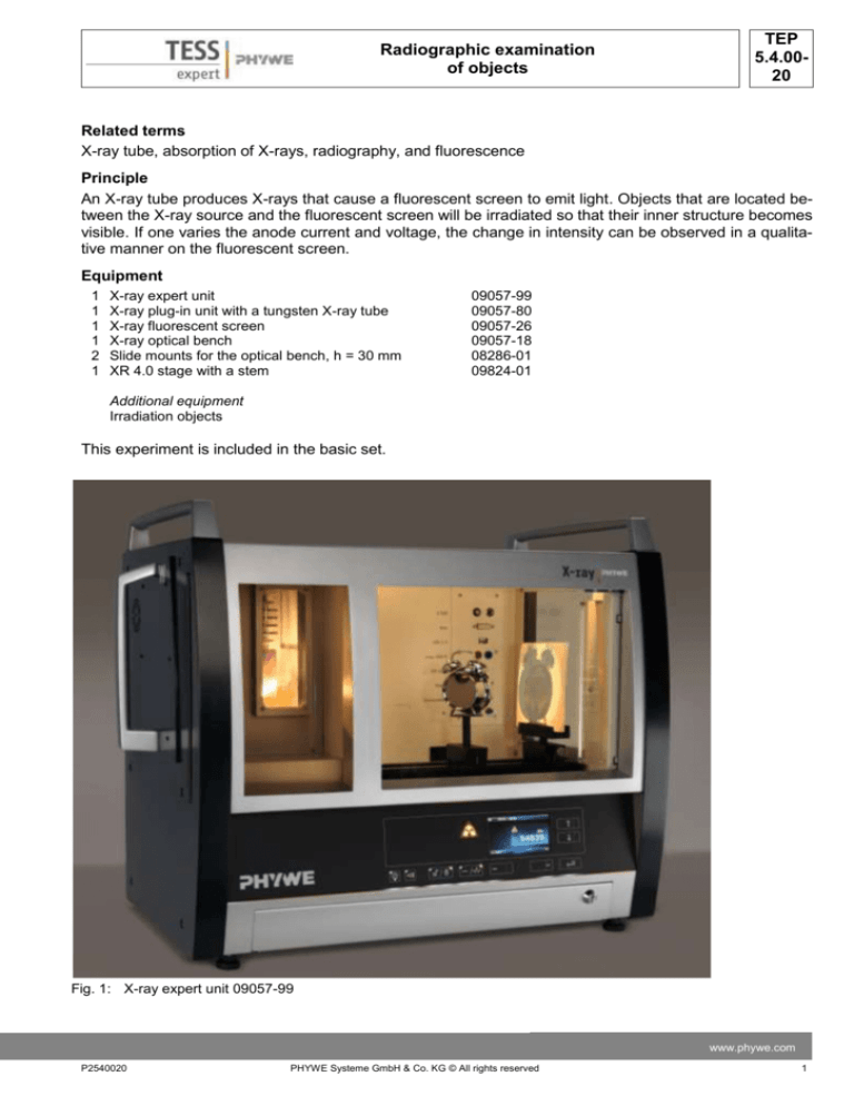
Fig. 1: X-ray expert unit 09057-99
www.phywe.com
P2540020
PHYWE Systeme GmbH & Co. KG © All rights reserved
1
TEP
5.4.0020
Radiographic examination
of objects
Tasks
1. X-ray an object and observe the result on the fluorescent screen.
2. Vary the anode current and voltage and observe the result on the fluorescent screen.
Set-up
If a goniometer is installed in the experiment chamber, it should be removed if possible.
Install the optical bench and position the fluorescent screen in its holder on the optical bench as far to
the right as possible. In order to position the various objects in front of the fluorescent screen in a stable
manner, we recommend using the object stages.
Procedure
Position the object directly in front of the fluorescent screen, or at a distance from the screen, right in the
beam path. If it is positioned at a distance from the screen, it will be magnified but at the same time it will
also lose sharpness. You will obtain a high-contrast image with maximum anode voltage (35 kV) and
maximum anode current (1.0 mA).
Now, close the door and proceed as follows:
-
Lock the door with the aid of this button:
-
Activate the X-radiation with this button:
-
The display shows:
Adjusting the anode voltage and current:
2
-
Press the button under “Menu” (display).
-
In the following window, select the option “Xray parameters” (use the arrow keys for the selection).
PHYWE Systeme GmbH & Co. KG © All rights reserved
P2540020
TEP
5.4.0020
Radiographic examination
of objects
-
Select the parameter that you would like to
change.
-
Confirm your selection with “Enter”.
-
Change the current value that is displayed with
the aid of the arrow keys.
-
Confirm with “Enter”.
The new parameters will now be displayed.
Taking a picture with a digital camera:
Fasten the camera to a slide mount on the optical bench.
Switch it to night mode and deactivate the flash.
Either darken the room completely or cover the unit with its cover.
We recommend starting the camera with the self-timer so that the picture does not blur during the
handling of the camera.
Theory
X-rays are invisible to the human eye. In order to be able to perceive them nonetheless, they are “converted” into visible light by fluorescence and with the aid of certain materials. These substances absorb
the X-radiation and enter into an excited state. When they fall back into the ground state, they partly emit
this energy. The loss in energy results in a changed wavelength of the emitted light: The wavelength is
longer and now in the visible range. Nowadays, mostly zinc sulphide is used as the luminescent agent
on the screen.
X-rays penetrate objects that are impenetrable for visible light. Visible light is absorbed to a far lower extent. The absorption depends on the thickness and type of the material. While in the past X-rays were
even used to check whether a shoe fits well, we now know about the harmful effects of the radiation. At
airports, it is used in order to inspect luggage.
When X-rays with the intensity I0 hit matter of the thickness d, the intensity I of the transmitted radiation
is as follows in accordance with the law of absorption (see experiment P2541101):
I I 0e , Z d
(1)
I: intensity of the radiation behind the absorber
I0: initial intensity of the radiation
www.phywe.com
P2540020
PHYWE Systeme GmbH & Co. KG © All rights reserved
3
TEP
5.4.0020
Radiographic examination
of objects
μ: linear absorption coefficient
d: thickness of the material
Equation (1) directly shows that the intensity of the radiation behind the absorber also depends on the
thickness of the absorber.
The linear absorption coefficient μ [cm-1] depends on the wavelength λ of the radiation as well as on the
atomic number Z of the absorbing matter. The absorption capacity of a material increases drastically
when the wavelength or atomic number of the absorber increases.
Evaluation and results
Task 1: X-ray an object and observe the result on the fluorescent screen.
X-ray of a digital alarm clock:
The relatively sharp image of the digital alarm clock can be seen on the fluorescent screen (Fig. 1). The
parts that contain metals, in particular, are clearly visible.
Inside the alarm clock, the wires can be seen very clearly
because they consist of metal that has a considerably
higher atomic number than the surrounding plastic. Plastic consists mainly of carbon, hydrogen, and oxygen.
Note: If you would like to take a picture of an object that
“floats in space”: Place it on a kitchen sponge. The
sponge transmits nearly the entire X-radiation.
X-ray of a snail shell:
The inner spindle of the snail shell is clearly visible in
Figure 2.
Figure 1 shows that the transmission depends on the
thickness of the absorber. The snail shell consists completely of the same material, but in the area of the spindle there is more “mass” between the X-ray source and
the screen. This is why this area is more clearly visible
due to its higher absorption level.
Fig. 1: Radiography of a digital alarm clock.
Fig. 2: Radiography of the shell of a common whelk
4
PHYWE Systeme GmbH & Co. KG © All rights reserved
P2540020
TEP
5.4.0020
Radiographic examination
of objects
Task 2: Vary the anode current and voltage and observe the result on the fluorescent screen.
When the anode current is reduced, the image gets darker. The same happens when the anode voltage
is reduced (Fig. 3).
Fig 3: The shell of a common whelk with different anode voltages
Note:
A wide range of different objects can be used to demonstrate the effect of X-rays. Particularly impressive
results can be achieved either with objects that consist of several different materials of different absorption capacities or with objects with a varying material thickness. Examples:
Fig. 4: Radiography of a pocket calculator and of a gleditsia pod.
www.phywe.com
P2540020
PHYWE Systeme GmbH & Co. KG © All rights reserved
5
TEP
5.4.0020
6
Radiographic examination
of objects
PHYWE Systeme GmbH & Co. KG © All rights reserved
P2540020

