Exercise4
advertisement
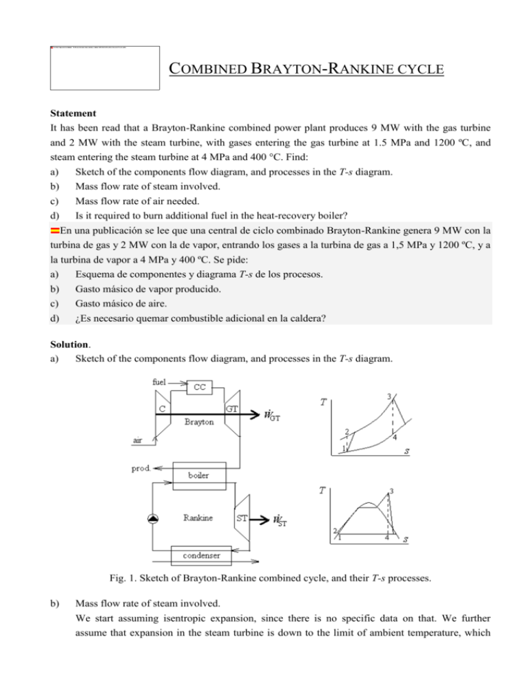
COMBINED BRAYTON-RANKINE CYCLE Statement It has been read that a Brayton-Rankine combined power plant produces 9 MW with the gas turbine and 2 MW with the steam turbine, with gases entering the gas turbine at 1.5 MPa and 1200 ºC, and steam entering the steam turbine at 4 MPa and 400 °C. Find: a) Sketch of the components flow diagram, and processes in the T-s diagram. b) Mass flow rate of steam involved. c) Mass flow rate of air needed. d) Is it required to burn additional fuel in the heat-recovery boiler? En una publicación se lee que una central de ciclo combinado Brayton-Rankine genera 9 MW con la turbina de gas y 2 MW con la de vapor, entrando los gases a la turbina de gas a 1,5 MPa y 1200 ºC, y a la turbina de vapor a 4 MPa y 400 ºC. Se pide: a) Esquema de componentes y diagrama T-s de los procesos. b) Gasto másico de vapor producido. c) Gasto másico de aire. d) ¿Es necesario quemar combustible adicional en la caldera? Solution. a) Sketch of the components flow diagram, and processes in the T-s diagram. Fig. 1. Sketch of Brayton-Rankine combined cycle, and their T-s processes. b) Mass flow rate of steam involved. We start assuming isentropic expansion, since there is no specific data on that. We further assume that expansion in the steam turbine is down to the limit of ambient temperature, which we take as T0=288 K by lack of specific data, in spite of the fact that, in normal practice, a few degrees above the maximum year-around environmental temperature should be consider, to guaranty all-year operation with a reasonable temperature jump across the condenser, i.e. at least some T1>300 K (and a vapour pressure of p1>3.6 kPa, instead of p1>1.7 kPa corresponding to T1>288 K). Using Antoine's fitting (or looking up in the steam tables): B 3985 pv (T ) pu exp A (1 kPa) exp 16.54 1.7 kPa C T / Tu 39 288 The mass flow rate of steam involved, mST , is obtained from the work delivered by the steam turbine. Neglecting the work consumed by the pumps, the equation is WST mST h3 h4 ST . The enthalpy value of the steam at the turbine inlet, taking as reference hR=0 for liquid water at its triple point (TR=273 K, pR=0.6 kPa), as usual, can be approximated with the perfect-substance model by h3=hR+hLV,R+cp,v(T3TR)=0+2500+1.9(4000)=3260 kJ/kg, what can be compared with the most exact value (NIST) of h3=3213 kJ/kg. Enthalpy at turbine outlet might be found graphically in a Mollier diagram, by intersection of the vertical from point 3, s3=6.77 kJ/(kg·K) with the isobar of p4=p1=1.7 kPa, obtaining h4=1950 kJ/kg. However, to avoid graphical solutions, we apply the perfect-substance model, which, although more lengthy, it is easily programmable: first the vapour mass fraction at 4 is found from s4=s3=s4L(1x4)+s4Vx4, with s3=sR+hLV,R/TR+cp,vln(T3TR)Rln(p3pR)= 0+2500/273+1.9ln(773/273)0.46ln(4000/0.6)= 6.77 kJ/(kg·K), s4L=sR+cp,Lln(T4TR)= 0+4.2ln(288/273)= 0.22 kJ/(kg·K), and s4V=sR+hLV,R/TR+cp,vln(T4TR)Rln(p4pR)= 0+2500/273+1.9ln(288/273)0.46ln(1.7/0.6)= 8.74 kJ/(kg·K); i.e. x4=(s4s4L)/(s4Vs4L)=(6.770.22)/(8.740.22)=0.77, too small a value for practical steam turbines (where only values greater than x4=0.85 or so are tolerated to avoid mechanical degradation of the blades by high-speed droplet impingement). Finally h4=h4L(1x4)+h4Vx4, with h4L=hR+cp,L(T4TR)=0+4.2(288-273)=63 kJ/kg and h4V=hR+hLV,R+cp,V(T4TR)=0+2500+1.9(288-273)=2530 kJ/kg, so that h4=63(10.77)+2530·0.77=1960 kJ/kg. The mass flow rate of steam involved is finally obtained from WST mST h3 h4 ST , with WST 2 MW and a result: mST WST 2000 1.54 kg/s h3 h4 3260 1960 i.e. at least 1.54 kg/s of steam would have to be processed in the steam turbine to generate 2 MW, with a real value somehow larger in practice if a more practical value for T4 had been chosen (notice that with this change, the steam at the turbine outlet would not be so 'wet' (i.e. x4 would be more practical). Furthermore, a practical isentropic efficiency of some 85% for the turbine would further increase the required steam flow-rate. c) Mass flow rate of air needed. Now we have to solve the gas turbine. As above, we assume isentropic compression and expansion, since there is no specific data on that. The mass flow rate of air involved, mGT , is obtained from the work delivered by the gas turbine: WGT mGT 1 1 0.4 T T1 12 288 15 1.4 624 K c p T3 T4 c p T2 T1 with 2 1 1 0.4 1.4 679 K T4 T3 / 12 1473 /15 with a result of: mGT WGT 9000 19.6 kg/s c p T3 T4 c p T2 T1 1 1473 679 1 624 288 i.e., a minimum of 19.6 kg/s of air must be compressed (the amount of fuel added is insignificant to the mass flow rate); in practice, with isentropic efficiencies around 0.85, some 30% or 40% more air would be needed to produce the 9 MW. d) Is it required to burn additional fuel in the heat-recovery boiler? First of all, we must check that the exhaust from the gas turbine is hotter than the steam to be produced. Assuming isentropic compression and expansion, the product gases exit at T4=679 K and the steam must be produced at T3=(400+273)=673 K < 679 K; i.e. there are 6 K of approach temperature jump, not too much for this preliminary analysis, but acceptable because, in practice, gases will be hotter at the exhaust due to energy degradation in the gas turbine. Secondly, we must check that the exhaust from the gas turbine has enough enthalpy to generate all the required vapour. The required heat for the boiler is QB mST h3 h2 ST 1.54 3260 63 4.9 MW whereas from the gas-turbine exhaust we can recover up to mGT c p T4,GT Tpv (T3 ),ST , where it has been taken into account the fact that the temperature profiles within the heat exchanger cannot cross each other, and the usual approximation of limiting the temperature approach up to the vaporisation point, has been adopted. Finding the boiling temperature at 4 MPa by Antoine's equation, Tpv (T3 ) 522 K , and substituting we get mGT c p T4,GT Tpv (T3 ) =19.6·1·(679522)= 3.1 MW, what is not enough for the 5 MW needed, so we must revise our assumptions. NEW MODEL Let us introduce practical isentropic efficiencies of the order =0.85 for all compressors and expanders, as well as the more realistic condenser pressure of 3.6 kPa, corresponding to T1=300 K, as said in the beginning. With these new assumptions, the isentropic vapour fraction is obtained from s4s=s3=s4L(1x4s)+s4Vx4s, with s4L=sR+cp,Lln(T4TR)=0+4.2ln(300/273)=0.40 kJ/(kg·K), and s4V=sR+hLV,R/TR+cp,vln(T4TR)Rln(p4pR)= 0+2500/273+1.9ln(300/273)0.46ln(3.6/0.6)= 8.48 kJ/(kg·K); i.e. x4s=(s4ss4L)/(s4Vs4L)=(6.770.40)/(8.480.40)=0.79, and now h4s=h4L(1x4s)+h4Vx4s=2020, but now ST=(h3h4)/(h3h4s)=0.85 and thus h4=2210 kJ/kg, with a more reasonable x4=(h4h4L)/(h4Vh4L)=0.86. The mass flow rate of steam involved is finally obtained from WST mST h3 h4 ST , with WST 2 MW and a result: mST WST 2000 1.91 kg/s h3 h4 3260 2210 instead of the 1.54 kg/s of steam previously found. Mass flow rate of air needed now changes because, for the gas turbine now: 1 1 T4 T3 1 T 1 1 1473 1 0.85 1 0.4 798 K 151.4 12 0.4 1.4 1 15 1 12 T2 T1 1 288 1 683 K C 0.85 1 and consequently: mGT WGT 9000 32.1 kg/s c p T3 T4 c p T2 T1 1 1473 683 1 798 288 what is a big increase over the 19.6 kg/s previously found. Now we need more heat to vaporise the greater amount of steam: QB mST h3 h2 ST 1.91 3260 113 6.0 MW but on the other hand we have plenty of heat available now: mGT c p T4,GT Tpv (T3 ) 32.11 798 522 8.9 MW . Comments In conclusion, the statement of this problem seems realistic, and the exercise has shown that, sometimes, drastic simplifying assumptions have to be revised if results fall within the bounds of admissible uncertainty. Back

