DOCX - Montana State University
advertisement
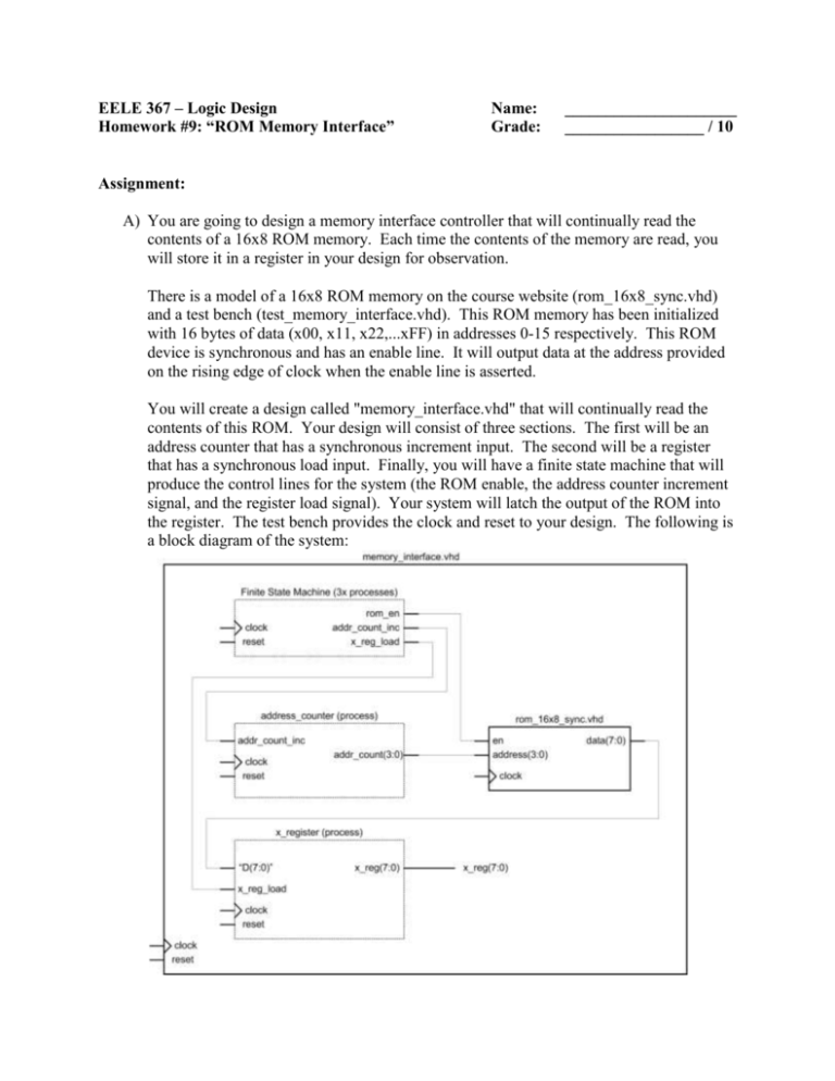
EELE 367 – Logic Design Homework #9: “ROM Memory Interface” Name: Grade: _____________________ _________________ / 10 Assignment: A) You are going to design a memory interface controller that will continually read the contents of a 16x8 ROM memory. Each time the contents of the memory are read, you will store it in a register in your design for observation. There is a model of a 16x8 ROM memory on the course website (rom_16x8_sync.vhd) and a test bench (test_memory_interface.vhd). This ROM memory has been initialized with 16 bytes of data (x00, x11, x22,...xFF) in addresses 0-15 respectively. This ROM device is synchronous and has an enable line. It will output data at the address provided on the rising edge of clock when the enable line is asserted. You will create a design called "memory_interface.vhd" that will continually read the contents of this ROM. Your design will consist of three sections. The first will be an address counter that has a synchronous increment input. The second will be a register that has a synchronous load input. Finally, you will have a finite state machine that will produce the control lines for the system (the ROM enable, the address counter increment signal, and the register load signal). Your system will latch the output of the ROM into the register. The test bench provides the clock and reset to your design. The following is a block diagram of the system: Your state machine will drive the control lines for all of the subsections and components. The FSM will have three outputs (rom_en, addr_count_inc, and x_reg_load. You can accomplish this using four states as shown in the following state diagram. Note in this diagram that the outputs are Moore type. The output signal names are not shown in the state bubbles to save space. Instead, just their values are given and the order is provided on the right. Your final simulation outputs should look like this: Deliverables: - The VHDL for the top level of your design (memory_interface.vhd) A plot of your ModelSim simulation results showing all signals just as shown above.
