24) DigitalResolution_4_12_13
advertisement
ECEN 4616/5616
4/12/2013
The effect of Detector Resolution on Images
The response of an imaging system to a point source is the Point Spread
Function (PSF). This is, in fact, the impulse response of system.
Considering only the (well-corrected) optical part:
1. The PSF is essentially invariant over the optics’ Field of View (FOV) – this
is part of the definition of “well-corrected”.
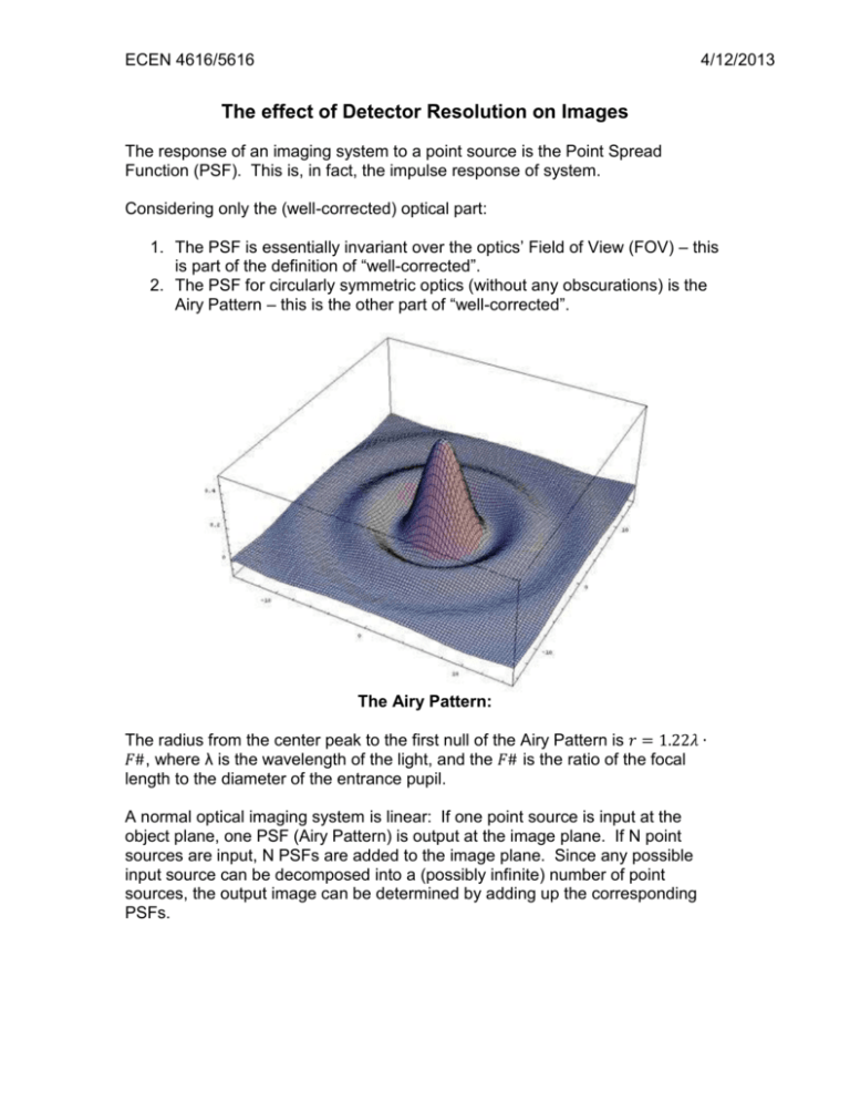
2. The PSF for circularly symmetric optics (without any obscurations) is the
Airy Pattern – this is the other part of “well-corrected”.
The Airy Pattern:
The radius from the center peak to the first null of the Airy Pattern is 𝑟 = 1.22𝜆 ∙
𝐹#, where λ is the wavelength of the light, and the 𝐹# is the ratio of the focal
length to the diameter of the entrance pupil.
A normal optical imaging system is linear: If one point source is input at the
object plane, one PSF (Airy Pattern) is output at the image plane. If N point
sources are input, N PSFs are added to the image plane. Since any possible
input source can be decomposed into a (possibly infinite) number of point
sources, the output image can be determined by adding up the corresponding
PSFs.
ECEN 4616/5616
4/12/2013
What we’ve just described is the convolution operation; So the image of an
optical system can be determined by the convolution of the input object
distribution with the PSF:
𝑖(𝑥, 𝑦) = 𝑜(𝑥, 𝑦) ∗ 𝑝𝑠𝑓(𝑥, 𝑦)
(eq. 1)
The convolution description only is valid if the PSF is essentially the same over
the image. For space-variant systems (where the PSF does vary considerably),
the summation description is still valid.
The Convolution Theorem in Fourier Transforms allows us to write the (space
invariant) imaging equation (eq. 1) in terms of the Fourier Transform of the
image, object, and PSF:
𝐼(𝑢, 𝑣) = 𝑂(𝑢, 𝑣) ∙ 𝑃𝑆𝐹(𝑢, 𝑣)
(eq. 2)
Where 𝑢, 𝑣 are spatial frequencies in the 𝑥, 𝑦 directions and the operation
between the Object and PSF transforms is an element-by-element multiplication.
Since the Optical Transfer Function (OTF) is the Fourier Transform of the psf, we
have:
𝑃𝑆𝐹 ≡ 𝐹{𝑝𝑠𝑓} = 𝑂𝑇𝐹, 𝑎𝑛𝑑 𝑀𝑇𝐹 = |𝑂𝑇𝐹|
Then equation 2 insures that the Image is a (spatial frequency) band-limited copy
of the Object, with the Fourier Transform of the psf acting as the limit. From
Abbe’s criteria, we know that the maximum spatial frequency that can exist in the
image of our “perfect” (i.e., no aberrations) optical system is:
𝑓𝑀𝐴𝑋 =
𝑁𝐴
𝜆
≅
1
2 𝐹# 𝜆
(eq. 3)
And the period of that frequency is:
𝑃𝑀𝐼𝑁 =
1
𝑓𝑀𝐴𝑋
= 2 𝐹# 𝜆
(eq. 4)
(which is about 80% of the diameter of the Airy Pattern to the first null ring.)
The Aerial Image:
So far, equations 3 & 4 describe the optical image – often called the “aerial
image”, since it exists just above the detector.
Sampling Theorem:
The sampling theorem (which we won’t derive) demonstrates that the value of a
continuous function, that has a limiting spatial frequency of 𝑓𝑀𝐴𝑋 , can be
uniquely recovered from a set of regularly spaced samples of the function, with
spacing of ∆𝑥 = 1⁄2𝑓 . This is known as the Nyqist sampling rate, and 𝑓𝑀𝐴𝑋 is
𝑀𝐴𝑋
called the Nyquist frequency for a sample spacing of Δx. (These are named for
Harry Nyquist, an engineer at Bell Laboratories in the 1950’s and 1960s.)
ECEN 4616/5616
4/12/2013
Just because the signal can be recovered from this sampling rate, does not
mean that it is easy or that the Nyquist rate should be used. The only method of
recovering the frequencies near the Nyquist limit involves replacing every
sampled data point with a sinc function, centered on that point and whose value
is zero at every other point (we also won’t derive this):
For example, a signal, s(x), sampled at integer values of x would be
reconstructed from those samples by a summation of sinc functions:
∞
𝑠(𝑥) = ∑ 𝑠(𝑘∆𝑥)𝑠𝑖𝑛𝑐(2𝜋𝑓𝑀𝐴𝑋 [𝑥 − 𝑘∆𝑥])
𝑘=−∞
The sinc function for the sample at k=0 would be:
1
0.8
0.6
0.4
0.2
0
-0.2
-0.4
-5
-4
-3
-2
-1
0
1
2
3
4
5
Note that the interpolating function is zero at every sample point except x = 0.
ECEN 4616/5616
4/12/2013

