TEP
5.4.12
-01
K and L edge absorption – Moseley’s law
and the Rydberg constant
Related topics
Bremsstrahlung, characteristic X-radiation, Bragg scattering, Bohr model, energy levels, Moseley’s law,
Rydberg frequency, and screening constant
Principle
Samples of various thicknesses are irradiated with the polychromatic X-rays of a copper X-ray tube. The
radiation that passes through the samples is analysed with the aid of a monocrystal. The Rydberg constant is calculated based on the glancing angles of the absorption edges.
Equipment
1
1
1
1
1
1
1
1
XR 4.0 expert unit
09057-99
X-ray goniometer
09057-10
X-ray plug-in unit with a Cu X-ray tube 09057-50
Counter tube, type B
09005-00
X-ray lithium fluoride crystal, in holder 09056-05
X-ray diaphragm tube, 2 mm
09057-02
X-ray diaphragm tube, 5 mm
09057-03
X-ray chemicals set for edge absorption 09056-04
1
1
1
1
1
Silver nitrate, cryst., 15 g
Mortar and pestle, 70 ml, porcelain
Microspoon, steel
measure XRm 4.0 X-ray software
Data cable USB, plug type A/B
30222-00
32603-00
33393-00
14414-61
14608-00
Additional equipment
PC, Windows® XP or higher
This experiment is included in the “XRS 4.0 X-ray structural analysis” upgrade set.
Note: Alternatively, this experiment can also be performed with an iron X-ray tube.
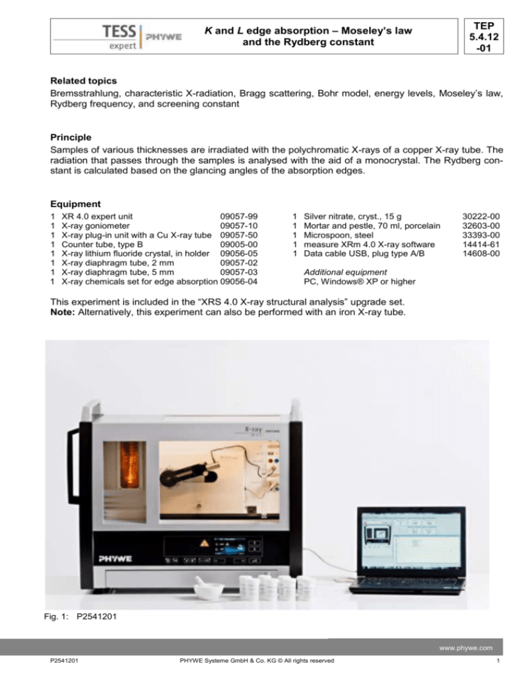
Fig. 1: P2541201
www.phywe.com
P2541201
PHYWE Systeme GmbH & Co. KG © All rights reserved
1
TEP
5.4.12
-01
K and L edge absorption – Moseley’s law
and the Rydberg constant
Safety instructions
When handling chemicals, you should wear suitable protective
gloves, safety goggles, and suitable clothing. Please refer to the
appendix for detailed safety instructions.
Tasks
1. Analyse the copper X-radiation with the aid of a LiF
monocrystal and as a function of the Bragg angle without
and with several K edge absorption samples as absorbers. Determine the K absorption edges of different absorbers based on the spectra.
2. Calculate the Rydberg constant and the screening constant based on the energy values of the K absorption Fig. 2: Connectors in the experiment
chamber
edges.
3. Proceed as described for task 1, but this time with various samples for L edge absorption.
4. Calculate the Rydberg constant based on the energy values of the L absorption edges.
Set-up
Connect the goniometer and the Geiger-Müller counter tube to their respective sockets in the experiment
GM-counter
tube
Goniometer at
the end position
Diaphragm tube
Counter tube
diaphragm
Mounted
crystal
Fig. 3: Set-up of the goniometer
2
PHYWE Systeme GmbH & Co. KG © All rights reserved
P2541201
TEP
5.4.12
-01
K and L edge absorption – Moseley’s law
and the Rydberg constant
chamber (see the red markings in Fig. 2). The goniometer block with the analyser crystal should be located at the end position on the right-hand side.
Fasten the Geiger-Müller counter tube with its holder to the back stop of the guide rails. Do not forget
to install the diaphragm in front of the counter tube
(see Fig. 3).
Insert a diaphragm tube with a diameter of 2 mm
(without an absorber) or 5 mm (with an absorber) in- Fig. 4: Connection of the computer
to the beam outlet of the tube plug-in unit for the
collimation of the X-ray beam.
For calibration: Make sure, that the correct crystal
is entered in the goniometer parameters. Then, select “Menu”, “Goniometer”, “Autocalibration”. The
device now determines the optimal positions of the
crystal and the goniometer to each other and then
the positions of the peaks.
Note
Details concerning the operation of the X-ray unit
and goniometer as well as information on how to
handle the monocrystals can be found in the respective operating instructions.
For setting the
X-ray tube
For setting the
goniometer
Procedure
- Connect the X-ray unit via USB cable to the USB
port of your computer (the correct port of the Xray unit is marked in Fig. 4).
- Start the “measure” program. A virtual X-ray unit
will be displayed on the screen.
Fig. 5: Part of the user interface of the software
- You can control the X-ray unit by clicking the various features on and under the virtual X-ray unit.
Alternatively, you can also change the parameters at the real X-ray unit. The program will automatically adopt the settings.
- Click the experiment chamber (see the red marking in Figure 5) to change the parameters for the experiment. Select the settings as shown in the overview for the various experiments.
Glancing angle ϑ = 5°-26°. For the recording
without any absorber, use the diaphragm tube
Overview of the settings of the goniometer
with a diameter of 2 mm. If an absorber is used,
and X-ray unit:
use the diaphragm tube with a diameter of 5
2:1 coupling mode
mm.
Scanning range: 4°-21°
- If you click the X-ray tube (see the red marking
Angle step width 0.1°
in Figure 5), you can change the voltage and
Anode voltage UA = 35 kV; anode current
current of the X-ray tube. Select the settings as
IA = 1 mA
shown in Figure 6.
Recording without an absorber
- Start the measurement by clicking the red circle
Gate time 2 s
Recording with a K edge absorber
Gate time 3 s
Recording with an L edge absorber
Gate time 6 s
www.phywe.com
P2541201
PHYWE Systeme GmbH & Co. KG © All rights reserved
3
TEP
5.4.12
-01
K and L edge absorption – Moseley’s law
and the Rydberg constant
Note
Never expose the Geiger-Müller counter tube to the
primary X-radiation for an extended period of time.
Sample preparation:
The thickness of the samples should be between 0.2
and 0.4 mm. If the samples are not thick enough, the
edge absorption effect cannot be made visible. On
the other hand, samples that are too thick absorb
nearly the entire primary beam intensity. This is why
the following method is recommended for preparing
samples of a suitable thickness: First, pulverise the
samples with the aid of a mortar. Then, use an office Fig. 6: Voltage and current settings
punch and punch several sheets of paper of a suitable thickness (approximately 3 layers of standard
printing paper) and seal the hole on one side with some transparent adhesive tape (see Fig. 7a). The re-
Fig. 7a-d: Sample preparation; a: perforated paper (3 layers) with adhesive tape; b: filling in the powder; c: smoothing the surface; d: fastening on the diaphragm tube
sult is a little “pot”. Fill the sample powder into the
pot with a spatula and smooth the surface. Seal the
pot with another piece of transparent adhesive tape.
Then, fasten the strip of paper that has been cut to
size in front of the diaphragm tube (aperture diameter: 5 mm) with some transparent adhesive tape.
Theory
When X-rays interact with matter, they lose energy
due to Compton scattering, pair production, and photoelectric effects. The respective strength of these
three effects depends on the energy of the radiation.
In the range of energy that is available during this
experiment, the photoelectric effect plays the most
important role. Figure 8 shows the schematic course
of the transmission T as a function of the radiation
Fig. 8: Schematic course of the transmission T as a
energy E. The cause of the irregularity that is known
function of the energy E in the area of an absorpas “edge absorption” is the photoelectric effect.
tion edge
The binding energy En of an electron on the nth shell
is approximately:
4
PHYWE Systeme GmbH & Co. KG © All rights reserved
P2541201
TEP
5.4.12
-01
K and L edge absorption – Moseley’s law
and the Rydberg constant
En
me e 4
Z 2 12
2 2
8 0 h
n
where
Electron mass
me
Elementary charge
e
Planck's constant
h
Dielectric constant
ε0
Atomic number
Z
Screening constant
σ
Principle quantum number n
(1)
= 9.1091∙10-31 kg
= 1.6021∙10-19 As
= 6.6256∙10-34 Js
= 8.8544∙10-12 N-1m-2C2
With the introduction of the Rydberg constant R:
R
me e 4
3.28989 1015 s 1
8 02 h 3
(2)
equation (1) becomes:
E n R h Z
2
1
n2
(3)
For electrons on the K shell (n = 1), the screening constant is σ ~= 1.
Calculation of the energy based on the glancing angles:
Using the Bragg equation
2d sin n (n = 1, 2, 3,…)
(4)
(d = 201.4 pm = interplanar spacing (002) of the LiF crystal)
with n = 1 and together with the energy equation
E h f
hc
(5)
(c = 2.998∙108 ms-1 = velocity of light)
we finally obtain the energy (n = 1) based on the glancing angles of the absorption edges:
E
hc
2d sin
(6)
Table 1 shows the ϑ values of the absorption edges of various absorbers that were taken from Figure 9.
Equation (6) was used to calculate the energy values EK of the associated K shells. For comparison, the
corresponding literature values are also provided.
Equation (3) is converted in order to calculate the Rydberg constant R.
Z
1
Rh
E
(with n = 1)
(7)
www.phywe.com
P2541201
PHYWE Systeme GmbH & Co. KG © All rights reserved
5
TEP
5.4.12
-01
K and L edge absorption – Moseley’s law
and the Rydberg constant
Table 1: K edge energies
Zn
Ge
Se
Br
Rb
Sr
Ag
Z
ϑExp/° EK(exp.)/keV EK(lit.)/keV
30
32
34
35
37
38
47
18.6
16.1
14.0
13.2
11.6
11.0
6.8
9.65
11.10
12.72
13.48
15.31
16.13
25.99
9.66
11.10
12.66
13.47
15.20
16.10
25.51
Evaluation
Task 1: Analyse the copper X-radiation with the aid of a LiF monocrystal and as a function of the Bragg
Fig. 9: X-ray spectra of copper without any absorber (top curve) and with the
absorption edges of various elements
angle without and with several K edge absorption samples as absorbers. Determine the K absorption
edges of different absorbers based on the spectra.
Figure 9 shows the intensity I of the copper X-radiation as a function of the Bragg angle ϑ up to the
characteristic Kβ line. The top curve shows the spectrum without any absorber. All of the other curves
were recorded with an additional absorber sample. The higher atomic number of the absorber is, the
more the absorption edge is shifted towards smaller glancing angles.
6
PHYWE Systeme GmbH & Co. KG © All rights reserved
P2541201
TEP
5.4.12
-01
K and L edge absorption – Moseley’s law
and the Rydberg constant
Task 2: Calculate the Rydberg constant and the screening constant based on the energy values of the K
absorption edges.
With the aid of equation (6), the edge absorption energy values can be obtained.
Figure 10 shows the function Z f
EK based on the energy values EK (exp.) of table 1.
Z
√𝐸𝐾
Fig. 10: Moseley line of the K edge absorption to determine the
Rydberg constant.
Based on the equation of the straight line
a
1
Rh
the following follows for the Rydberg constant:
2
1 E
R
3.311015 s 1
2
h Z
(8)
With the value for R and the EK (exp.) values of table 1, equation (3) leads to σ (K) = (3.5 ± 0.1) as the
mean value of the screening constant.
www.phywe.com
P2541201
PHYWE Systeme GmbH & Co. KG © All rights reserved
7
TEP
5.4.12
-01
K and L edge absorption – Moseley’s law
and the Rydberg constant
Task 3: Proceed as described for task 1, but this time
with various samples for L edge absorption.
Figure 11 shows bremsspectrum with the absorption
edges of elements of a higher atomic number. However, although three edges of the three L shells can
be expected in theory, only two can be seen. A separation of the absorption edges of the L2 and L3 subshells is not possible.
Task 4: Calculate the Rydberg constant based on the
energy values of the L absorption edges.
Table 2 shows the results concerning the L edge absorption. The literature value EL1,2 that is given for
comparison has been calculated by taking the mean
of the corresponding L1 and L2 values.
An evaluation with the aid of equation (1) does not
make any sense in this case, since – apart from the
Coulomb interaction – other interactive processes
must also be taken into account. Nevertheless, equation (1) is helpful in giving a rough idea of the screening of the electrons on L shells. According to (3) and
with n = 2 plus the experimental energy values in table 2, the following results:
Fig. 11: X-ray spectrum of copper with
the L absorption edges of various ele(9)
ments
K L1, 2 15 L3 20
The growth of the screening constant underlines the
decreasing influence of the nuclear potential on the electrons on the outer
shells.
Table 2: L edge energies
ϑ(L1,2)/°
EL1,2 exp./keV
EL1,2 lit./keV
ϑ(L3)/°
EL3 exp./keV
EL3 lit./keV
W (Z = 74)
15.5
11.52
11.82
Hg (Z = 80)
12.4
14.33
14.52
Pb (Z = 82)
11.6
15.31
15.53
Bi (Z = 83)
11.2
15.85
16.05
17.6
10.20
10.21
14.5
12.29
12.28
13.6
13.09
13.04
13.2
13.48
13.42
Figure 12 shows the linear course of the function Z f
8
E for L
L
1,2
PHYWE Systeme GmbH & Co. KG © All rights reserved
and L3 (9).
P2541201
K and L edge absorption – Moseley’s law
and the Rydberg constant
TEP
5.4.12
-01
84
83
82
81
80
79
78
77
76
75
74
73
3.1
3.2
3.3
3.4
3.5
3.6
3.7
3.8
3.9
4
4.1
Fig. 12: Moseley lines for the L edge absorption
“measure” software
In order to evaluate the measurements with the aid of the “measure” software, first convert the glancing
angles ϑ (crystal angle = x-axis) of the spectra into the corresponding energy values. To do so, proceed
as follows:
1. “Analysis”, “X-ray spectroscopy”, “Convert x-axis”, and “Energy (n = 1)”.
Moseley lines can be obtained from the converted spectra (Imp/s = f(E/keV) as follows:
2. Click “Analysis”, “X-ray spectroscopy”, and “Moseley straight line”.
The window “Moseley straight line” appears.
It offers two options: K and L edge absorption. Then, select the middle of the absorption edge as a
narrow band with the aid of the marker and click “Accept value”. If necessary, the area of the absorption edge can be zoomed with the aid of the zoom function.
If the absorber and its atomic number were entered into the start window prior to the actual measurement, the corresponding pair values for the edge energy and atomic number are displayed. The
latter can also be entered later into the additional window “Moseley straight line”.
Repeat this for the other spectra with different absorbers.
In order to generate the straight line, click “Generate Moseley line”.
The Rydberg constant can be determined by clicking “Analysis”, “X-ray spectroscopy”, and “Determine Rydberg constant”.
With “Display options”, “Channels”, and “Symbol”, the measuring points of the Moseley line can be
displayed if desired.
www.phywe.com
P2541201
PHYWE Systeme GmbH & Co. KG © All rights reserved
9
TEP
5.4.12
-01
K and L edge absorption – Moseley’s law
and the Rydberg constant
Disposal
Do not dispose of heavy-metal-containing waste via household waste.
Appendix
Hazard symbol, signal word
Hazard statements
Precautionary statements
--
-
H302: Harmful if swallowed
H332: Harmful if inhaled
-
Rubidium chloride (RbCl)
Germanium(IV) oxide (GeO2)
Silver (I) chloride (AgCl)
H400: Very toxic to aquatic life
P273: Avoid release to
the environment.
Warning
Zinc
Selenium
Danger
-
-
H301: Toxic if swalloed
H331 Toxic if inhaled
H373: Causes damage to
organs through prolonged
or repeated exposure
H413: May cause long
lasting harmful effects to
aquatic life
-
H315: Causes skin irritation
H319: Causes serious eye
irritation
H335: May cause respiratory irritation
P261: Avoid breathing
dust/fume/gas/mist/vapo
urs/spray.
P305 + P351 + P338: IF
IN EYES: Rinse cautiously with water for
several minutes. Remove contact lenses, if
present and easy to do.
Continue rinsing.
Potassium bromide (KBr)
Strontium sulphate (SrSO4)
10
PHYWE Systeme GmbH & Co. KG © All rights reserved
P2541201
K and L edge absorption – Moseley’s law
and the Rydberg constant
-
-
TEP
5.4.12
-01
-
Lead(IV) oxide (PbO2)
H272: May intensify fire;
oxidiser
H302: Harmful if swallowed
H332: Harmful if inhaled
H360: May damage fertility or the unborn child
H373: Causes damage to
organs through prolonged
or repeated exposure
H410: Very toxic to aquatic life with long lasting effects
Danger
P201: Obtain special instructions before use.
P220: Keep/Store away
from clothing/…/combustible materials.
P273: Avoid release to
the environment.
P308 + P313: IF exposed or concerned: Get
medical advice/attention.
Tungsten(IV) oxide (WO2)
H335: May cause respiratory irritation
-
H315: Causes skin irritation
H319: Causes serious eye
irritation
H335: May cause respiratory irritation
P261: Avoid breathing
dust/fume/gas/mist/vapo
urs/spray.
P305 + P351 + P338: IF
IN EYES: Rinse cautiously with water for
several minutes. Remove contact lenses, if
present and easy to do.
Continue rinsing.
Warning
Bismuth(III) oxide (Bi2O3)
Warning
www.phywe.com
P2541201
11
PHYWE Systeme GmbH & Co. KG © All rights reserved
TEP
5.4.12
-01
12
K and L edge absorption – Moseley’s law
and the Rydberg constant
PHYWE Systeme GmbH & Co. KG © All rights reserved
P2541201


