18 – Power Electronics in Solar Energy Systems 4
Power Electronics in Solar Energy Systems
Part IV
I - Photovoltaic Systems’ Components
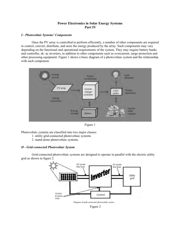
Once the PV array is controlled to perform efficiently, a number of other components are required to control, convert, distribute, and store the energy produced by the array. Such components may vary depending on the functional and operational requirements of the system. They may require battery banks and controller, dc–ac inverters, in addition to other components such as overcurrent, surge protection and other processing equipment. Figure 1 shows a basic diagram of a photovoltaic system and the relationship with each component.
Figure 1
Photovoltaic systems are classified into two major classes:
1. utility grid-connected photovoltaic systems
2. stand-alone photovoltaic systems.
II - Grid-connected Photovoltaic System
Grid-connected photovoltaic systems are designed to operate in parallel with the electric utility grid as shown in figure 2.
Figure 2
There are two general types of electrical designs for grid-connected PV power systems:
1. systems that interact with the utility power grid as shown in figure 3 and have no battery backup capability
Figure3
2. systems that interact and include battery backup as well, as shown in Figure 4
Figure 4
The latter type of system incorporates energy storage in the form of a battery to keep “critical load” circuits operating during utility outage. When an outage occurs, the unit disconnects from the utility and powers specific circuits of the load. If the outage occurs in daylight, the PV array is able to assist the load in supplying the loads.
The major component in both systems is the dc–ac inverter or also called the power conditioning system (PCS). Figure 2 shows the block diagram of such connection.
The inverter, used to convert photovoltaic dc energy to ac energy, is the key to the successful operation of the system, but it is also the most complex hardware.
The most important inverter characteristics requirements are:
1. To operate over a wide range of voltages and currents
2. To regulate output voltage and frequency,
3. To provide ac power with good power quality.
For the last twenty years, researchers have been working on developing different inverter topologies that satisfy the above listed requirements. The evolution of solid state devices such as
MOSFETs, IGBTs, microprocessors, PWM integrated circuits have allowed improvements on the inverter. However, more work is required to ensure quality control, reliability and lower cost since these are the key for a sustainable photovoltaic market.
A typical utility-interactive PV system is shown in figure 5 with metering to provide indication of system performance.
Figure 5
III – Stand – alone photovoltaic Systems
Stand-alone photovoltaic systems are usually a utility power substitute. They generally include solar charging modules, storage batteries, and controls/regulator as shown in figure 6. Ground or roof mounted systems will require a mounting structure, and if 120/240 volt ac power is desired, a dc to ac inverter will also be required. They are especially used in remote places that are not connected to the electrical main utility grid. In many stand-alone PV systems, batteries are used for energy storage. A charge controller is then used to control the whole system and prevent the battery from over-charging and over-discharging. Photovoltaic modules charge the battery during the day and supplies power to the load as needed.
Figure 6
Batteries
Batteries are often used in PV systems for storing energy produced by the PV array during day time and supplying it to electrical loads as needed (during night time or cloudy weather). Moreover, batteries are also needed in the tracker systems to keep the operation at MPP in order to provide electrical loads with stable voltages. Nearly, most of the batteries used in PV systems are deep cycle lead-acid.
These batteries have thicker lead plates that make them tolerate deep discharges. The thicker the lead plates, the longer the life span. The heavier the battery for a given group size, the thicker the plates and the better the battery will tolerate deep discharges.
All deep cycle batteries are rated in ampere-hour where Ampere-hour (AH) capacity is a quantity of the amount of usable energy it can store at nominal voltage. For example an ampere-hour is one ampere for one hour or 10 A for one-tenth of an hour and so forth. A good charge rate is approximately
10% of the total capacity of the battery per hour (i.e. 200 ampere-hour battery charged at 20A). This will reduce electrolyte loss and damage to the plates. A PV system may have to be sized to store a sufficient amount of power in the batteries to meet power demand during several days of cloudy weather. This is known as “days of autonomy”.
Charge Controller
The charge controller regulates the flow of electricity from the PV modules to the battery and the load. The controller keeps the battery fully charged without overcharging it. When the load is drawing power, the controller allows charge to flow from the modules into the battery, the load, or both. When the controller senses that the battery is fully charged, it stops the flow of charge from the modules. Many controllers will also sense when loads have taken too much electricity from batteries and will stop the flow until sufficient charge is restored to the batteries. This last feature can greatly extend the battery’s lifetime. However, controllers in stand-alone photovoltaic system are more complex devices that depend on battery state-of-charge, which in turn depends on many factors and is difficult to measure.
The controller must be sized to handle the maximum current produced.
Several characteristics should be considered before selecting a controller:
• Adjustable Setpoints.
• High voltage disconnect.
• Low voltage disconnect.
• Temperature compensation.
• Low voltage warning.
• Reverse current protection.
The controller should ensure that no current flows from the battery to the array at night.
IV – Factors Affecting Power Output
PV systems produce power in proportion to the intensity of sunlight striking the solar array surface. Thus there are some factors that affect the overall output of the PV system.
Temperature
Output power of a PV system reduces as the module temperature increases. For Crystalline modules, a typical temperature reduction factor recommended by CEC is 89% in the middle of spring or a fall day, under full light conditions.
Dirt and Dust
Dirt and dust can accumulate on the solar module surface, blocking some of the sunlight and reducing output. A typical annual dust reduction factor to use is 93%. J. P. Thornton showed that sand and dust can cause erosion of the PV surface which affects the system’s running performance by decreasing the output power to more than 10%.
DC – AC Conversion
Since the power from the PV array is converted back to ac as shown previously, some power is being lost in the conversion process, in addition to losses in the wiring. Common inverters used have peak efficiencies of about 88–90%. Thus a 100 Watts module under well controlled conditions is actually a 95
Watts module under normal condition. This power is then reduced due to the factors listed to:
Effect of Temperature: 95 × 0.89 = 85 Watts
Effect of Dirt and Dust: 85 × 0.93 = 79 Watts
Effect of Conversion: 79 × 0.90 = 71 Watts
V – System Design
The goal for a solar electric, or photovoltaic system is to provide high-quality, reliable renewable electrical power.
Criteria for a Quality PV System
• Be properly sized and oriented to provide electrical power
and energy.
• Good control circuit to reduce electrical losses, overcurrent protection, switches and inverters.
• Good charge controller and battery management system,
should the system contain batteries.
Design Procedures
The first task in designing a PV system is to estimate the system load. This is achieved by defining the power demand of all loads, the number of hours of use per day, and operating voltage.
From the load ampere-hours, and the given operating voltage for each load, the power demand is then calculated. For a stand-alone system, the system voltage is the potential required by the largest load. When ac loads dominate, the dc system voltage should be chosen to be compatible with the inverter input.
Power Conditioning System
The choice of the PCS has a great impact on the performance and economics of the system. The choice of PCS depends on the type of waveform produced which in turn depends on the method used for conversion as well as the filtering techniques of unwanted frequencies. Several factors must be considered when selecting or designing the inverter:
• The power conversion efficiency.
• Rated power.
• Duty rating; the amount of time the inverter can supply maximum load.
• Input voltage.
• Voltage regulation.
• Voltage protection.
• Frequency requirement.
• Power factor.
Battery Sizing
The amount of battery storage needed depends on the load energy demand and on weather patterns at the site. There is always a trade-off between keeping cost low and meeting energy demand.


