Specification - Aluminum Stop Logs
advertisement
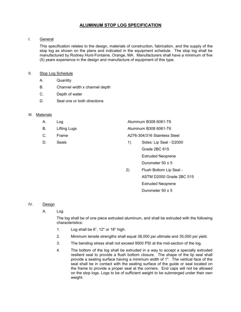
ALUMINUM STOP LOG SPECIFICATION I. General This specification relates to the design, materials of construction, fabrication, and the supply of the stop log as shown on the plans and indicated in the equipment schedule. The stop log shall be manufactured by Rodney Hunt-Fontaine, Orange, MA. Manufacturers shall have a minimum of five (5) years experience in the design and manufacture of equipment of this type. II. Stop Log Schedule A. Quantity B. Channel width x channel depth C. Depth of water D. Seal one or both directions III. Materials A. Log Aluminum B308 6061-T6 B. Lifting Lugs Aluminum B308 6061-T6 C. Frame A276-304/316 Stainless Steel D. Seals 1) Sides: Lip Seal - D2000 Grade 2BC 615 Extruded Neoprene Durometer 50 ± 5 2) Flush Bottom Lip Seal ASTM D2000 Grade 2BC 515 Extruded Neoprene Durometer 50 ± 5 IV. Design A. Log The log shall be of one piece extruded aluminum, and shall be extruded with the following characteristics: 1. Log shall be 6”, 12" or 18” high. 2. Minimum tensile strengths shall equal 38,000 psi ultimate and 35,000 psi yield. 3. The bending stress shall not exceed 9500 PSI at the mid-section of the log. 4. The bottom of the log shall be extruded in a way to accept a specially extruded resilient seal to provide a flush bottom closure. The shape of the lip seal shall provide a seating surface having a minimum width of 1". The vertical face of the seal shall be in contact with the seating surface of the guide or seal located on the frame to provide a proper seal at the corners. End caps will not be allowed on the stop logs. Logs to be of sufficient weight to be submerged under their own weight. B. Guide Slots Fabricated stainless steel guide slots shall be provided. These shall be to the proper dimensions including any mounting holes to ensure proper field adjustment. These guides shall extend the height as shown on the contract plans so to contain all logs. The bottom sill shall consist of a stainless steel formed channel either welded or bolted to the vertical side pieces. C. Seals Lip type seals shall be attached to the frame to restrict leakage. Under the condition which the log will be subjected to flow in both directions, the log and guide shall be provided with seals in both directions. D. Hardware All necessary attaching bolts and anchor bolts shall be stainless steel and furnished by the stop log manufacturer. V. Lifting Device One (1) lifting device shall be provided for each stop log width. The lifting device shall be equipped with a suitable eye bolt for crane operation. The device shall be guided by the slot of the guide extrusion, and shall be capable of securing and releasing the stop logs with the use of a lanyard from the operating floor. VI. Drawings for Approval Drawings showing dimensions and essential details required to locate and install the stop logs shall be submitted for the engineer's approval. VII. Installation The installation of all parts shall be done in a workmanlike manner and in accordance with detailed technical installation procedures supplied by the manufacturer. It shall be the contractor's responsibility to handle, store, and install the stop logs in strict accordance with manufacturer's drawings and recommendations.


