Supplementary material
advertisement
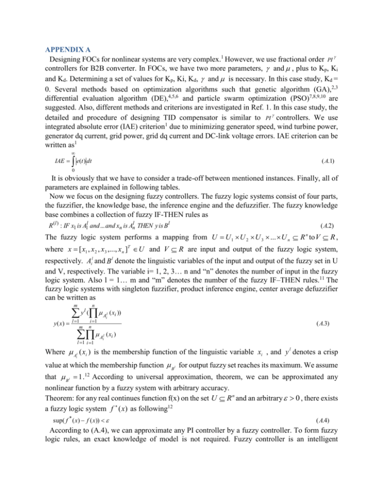
APPENDIX A Designing FOCs for nonlinear systems are very complex.1 However, we use fractional order PI controllers for B2B converter. In FOCs, we have two more parameters, and , plus to Kp, Ki and Kd. Determining a set of values for Kp, Ki, Kd, and is necessary. In this case study, Kd = 0. Several methods based on optimization algorithms such that genetic algorithm (GA),2,3 differential evaluation algorithm (DE),4,5,6 and particle swarm optimization (PSO)7,8,9,10 are suggested. Also, different methods and criterions are investigated in Ref. 1. In this case study, the detailed and procedure of designing TID compensator is similar to PI controllers. We use integrated absolute error (IAE) criterion1 due to minimizing generator speed, wind turbine power, generator dq current, grid power, grid dq current and DC-link voltage errors. IAE criterion can be written as1 IAE e(t ) dt ( A.1) 0 It is obviously that we have to consider a trade-off between mentioned instances. Finally, all of parameters are explained in following tables. Now we focus on the designing fuzzy controllers. The fuzzy logic systems consist of four parts, the fuzzifier, the knowledge base, the inference engine and the defuzzifier. The fuzzy knowledge base combines a collection of fuzzy IF-THEN rules as R (l ) : IF x1 is A1l and ... and xn is Anl THEN y is B l ( A.2) The fuzzy logic system performs a mapping from U U 1 U 2 U 3 ... U n R n to V R , where x [ x1 , x 2 , x3 ,..., x n ]T U and V R are input and output of the fuzzy logic system, respectively. Ail and B l denote the linguistic variables of the input and output of the fuzzy set in U and V, respectively. The variable i= 1, 2, 3… n and “n” denotes the number of input in the fuzzy logic system. Also l = 1… m and “m” denotes the number of the fuzzy IF–THEN rules.11 The fuzzy logic systems with singleton fuzzifier, product inference engine, center average defuzzifier can be written as n m A ( xi )) yl ( y ( x) l 1 m l i i 1 n ( A.3) A ( xi ) l 1 i 1 l i Where Al ( xi ) is the membership function of the linguistic variable xi , and y l denotes a crisp i value at which the membership function B l for output fuzzy set reaches its maximum. We assume that B l 1 .12 According to universal approximation, theorem, we can be approximated any nonlinear function by a fuzzy system with arbitrary accuracy. Theorem: for any real continues function f(x) on the set U R n and an arbitrary 0 , there exists a fuzzy logic system f (x) as following12 sup( f * ( x) f ( x)) ( A.4) According to (A.4), we can approximate any PI controller by a fuzzy controller. To form fuzzy logic rules, an exact knowledge of model is not required. Fuzzy controller is an intelligent controller and consists of information from expert. The used fuzzy logic controllers are MAMDANI and fuzzy membership functions are Gaussian for all of them. A0 A1 ... A250 -1 A499 ... A500 1 0 FIG. 1. Instance of the using membership function in this paper A Gaussian function h(x) can be written as h( x) ae (( x x0 ) / ) / 2 Where “a” is the maximum amplitude of h(x), x 0 is center of h(x) and is standard deviation. Information of input and output fuzzy controller as follow: The fuzzy controller in MSC side: Interval of input: [-50 400] Interval of output: [-500 15000] 1 a 1 The fuzzy controller in GSC side, related to error of DC-link voltage: Interval of input: [-2000 2000] Interval of output: [-1000 1000] 1 a 1 The fuzzy controller in GSC side, related to error of iq: Interval of input: [-2000 2000] Interval of output: [-1000 1000] 1 a 1 The number of rules is large. Therefore we bring them regardless. 2 TABLE I. PMSG parameters13 Parameters Value Unit Sg (Generator rated power) 1500 KVA F (frequency) 50 Hz Vg (Generator rated voltage) 575 V Rs(Stator resistance) 0.24 Mutual Inductance in d-axis, Ldm 0.0052 mH Mutual Inductance in q-axis, Lqm 0.0052 mH Permanent magnet flux 2.1669 V.s C (dc link capacitor) 6800 F Rf (Grid filter resistance) 0.0001 Lf (Grid filter inductance) 1 mH The obtained parameters related to designing controllers are as follow: TABLE II. Fractional PI controller characteristics Number of Kp Controllers Ki Kd 1 5 230.4147 1.1 0 2 70 200 0.45 0 4 3 150 1.93 0 TABLE III. TID controller characteristics TID controller characteristics 1 Kt 10 Ki 55 N 2.99 Kd 0 Also, the order of fractional order integrator is equal to 3.1. REFERENCES 1 2 3 4 5 6 7 Petras, I., “fractional order nonlinear systems, modeling, analysis and simulation,” Springer (2011). Chang, L. Y., and Chen, H.C., “tuning of fractional PID controllers using adaptive genetic algorithm for active magnetic bearing system,” WSEAS trans., 8, 226-236 (2009). Cao, J. Y., Liang, J., and Cao, B. G., “optimization of fractional order PID controllers based on genetic algorithms,” International Conference on Mach. Learning and Cybern, 9, 5686-5689 (2005). Bingul, Z., “a new PID tuning technique using differential evolution for unstable and integrating processes with time delay,” International Conference on Neural Information Processing (ICONIP ), 254-260 (2004). Arijit, B., Swagatam, D., Ajith, A., and Sambarta, D., “design of fractional-order PI D controllers with an improved differential evolution,” Journal of Engineering Applications of Artificial Intelligence, 22, 343-350 (2009). Chang, W., “two dimensional fractional order digital differential design by using differential evolution,” Journal of Digital Signal Processing, 19, 660-667 (2009). Cao, J. Y., and Cao, B. G., “design of fractional order controller based on particle swarm optimization,” International Journal of Control, Automation, and Systems, 6, 775-781 (2006). Maiti, D., Sagnik , B., and Konar, K., “design of a fractional order PID controller using particle swarm optimization technique,” International Conference on Recent Trends In Information Systems (2008). 9 Majid, Z., Masoud, K.G., Nasser, S., and Mostafa, P., “design of a fractional order PID controller for an AVR using particle swarm optimization,” Control Engineering Practice (2009). 10 Mukherjee, V., and Ghoshal, SP., “intelligent particle swarm optimized fuzzy PID controller for AVR system,” Journal of Electric Power Systems Research, 77, 1689-1698 (2007). 11 Sun, F.C., Sun, Z.Q., and Feng, G., “an adaptive fuzzy controller based on sliding mode for robot manipulators,” IEEE Trans., 29, 661–667 (1999). 12 Wang, L. X., “a course in fuzzy systems and control,” Prentice Hall, New York (1996). 13 Li, Sh., Haskew, T. A., Swatloski, R. P., and Gathings, W., “optimal and direct-current vector control of directdriven PMSG wind turbines,” IEEE Trans., 27, 2325-2337 (2012). 8
