3.3.1.A SSI Synchronous Counters
advertisement
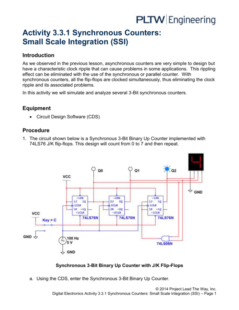
Activity 3.3.1 Synchronous Counters: Small Scale Integration (SSI) Introduction As we observed in the previous lesson, asynchronous counters are very simple to design but have a characteristic clock ripple that can cause problems in some applications. This rippling effect can be eliminated with the use of the synchronous or parallel counter. With synchronous counters, all the flip-flops are clocked simultaneously, thus eliminating the clock ripple and its associated problems. In this activity we will simulate and analyze several 3-Bit synchronous counters. Equipment Circuit Design Software (CDS) Procedure 1. The circuit shown below is a Synchronous 3-Bit Binary Up Counter implemented with 74LS76 J/K flip-flops. This design will count from 0 to 7 and then repeat. Synchronous 3-Bit Binary Up Counter with J/K Flip-Flops a. Using the CDS, enter the Synchronous 3-Bit Binary Up Counter. © 2014 Project Lead The Way, Inc. Digital Electronics Activity 3.3.1 Synchronous Counters: Small Scale Integration (SSI) – Page 1 b. With the RESET switch set to 5V, start the simulator. Verify that the circuit is working as expected. If the results are not what are expected, review your circuit and make any necessary correction. You may need to adjust the simulation speed to be able to observe the outputs changing. c. With the simulation running, toggle the RESET switch to GROUND. What effect does this have on the output? d. Toggle the RESET switch back to 5V. What effect does this have on the output? e. Finally, observe the HEX DISPLAY. Notice that, unlike the asynchronous counters analyzed in a previous lesson, the numbers displayed on the HEX DISPLAY transition smoothly. Why don’t these values jump between some count changes like they did with asynchronous counters? 2. Modify the circuit in step (1) to make it a Synchronous 3-Bit Binary Down Counter. Repeat steps 1a) through 1d) for this modified counter. 3. The circuit shown below is a Synchronous MOD-6 Binary-Up Counter implemented with 74LS76 J/K flip-flops. This design will count from 0 to 5 and then repeat. This MOD-6 counter utilizes a three-input NAND gate to generate an asynchronous reset to the clear inputs of the flip-flops when the count reaches six (110). Synchronous MOD-6 Binary Up Counter © 2014 Project Lead The Way, Inc. Digital Electronics Activity 3.3.1 Synchronous Counters: Small Scale Integration (SSI) – Page 2 4. Using the CDS, enter the Synchronous MOD-6 Binary Up Counter. a. Start the simulator, verify that the circuit is working as expected. If the results are not what are expected, review your circuit and make any necessary corrections. You may need to adjust the simulation speed to be able to observe the outputs changing. b. Modify this design to count from 0 to 4 and then repeat. Synchronous MOD-5 Binary Up Counter Conclusion 1. What are the advantages of Synchronous Counters over Asynchronous Counter? 2. Do Asynchronous Counters have any advantages? 3. What changes must be made to a 3-Bit counter to make it a 4-Bit counter? © 2014 Project Lead The Way, Inc. Digital Electronics Activity 3.3.1 Synchronous Counters: Small Scale Integration (SSI) – Page 3
![Lesson 8_3–Synchronous Counters[1]](http://s2.studylib.net/store/data/005727557_1-25e5d6e99f500ad17373ec48380a1b3c-300x300.png)

