Synchronous Counters: Design & Operation Tutorial
advertisement
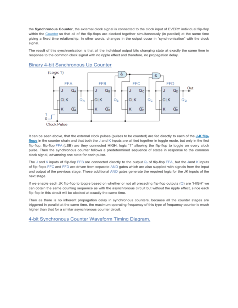
the Synchronous Counter, the external clock signal is connected to the clock input of EVERY individual flip-flop within the Counter so that all of the flip-flops are clocked together simultaneously (in parallel) at the same time giving a fixed time relationship. In other words, changes in the output occur in “synchronisation” with the clock signal. The result of this synchronisation is that all the individual output bits changing state at exactly the same time in response to the common clock signal with no ripple effect and therefore, no propagation delay. Binary 4-bit Synchronous Up Counter It can be seen above, that the external clock pulses (pulses to be counted) are fed directly to each of the J-K flipflops in the counter chain and that both the J and K inputs are all tied together in toggle mode, but only in the first flip-flop, flip-flop FFA (LSB) are they connected HIGH, logic “1” allowing the flip-flop to toggle on every clock pulse. Then the synchronous counter follows a predetermined sequence of states in response to the common clock signal, advancing one state for each pulse. The J and K inputs of flip-flop FFB are connected directly to the output QA of flip-flop FFA, but the Jand K inputs of flip-flops FFC and FFD are driven from separate AND gates which are also supplied with signals from the input and output of the previous stage. These additional AND gates generate the required logic for the JK inputs of the next stage. If we enable each JK flip-flop to toggle based on whether or not all preceding flip-flop outputs (Q) are “HIGH” we can obtain the same counting sequence as with the asynchronous circuit but without the ripple effect, since each flip-flop in this circuit will be clocked at exactly the same time. Then as there is no inherent propagation delay in synchronous counters, because all the counter stages are triggered in parallel at the same time, the maximum operating frequency of this type of frequency counter is much higher than that for a similar asynchronous counter circuit. 4-bit Synchronous Counter Waveform Timing Diagram. Because this 4-bit synchronous counter counts sequentially on every clock pulse the resulting outputs count upwards from 0 ( 0000 ) to 15 ( 1111 ). Therefore, this type of counter is also known as a 4-bit Synchronous Up Counter. However, we can easily construct a 4-bit Synchronous Down Counter by connecting the ANDgates to the Q output of the flip-flops as shown to produce a waveform timing diagram the reverse of the above. Here the counter starts with all of its outputs HIGH ( 1111 ) and it counts down on the application of each clock pulse to zero, ( 0000 ) before repeating again. Binary 4-bit Synchronous Down Counter As synchronous counters are formed by connecting flip-flops together and any number of flip-flops can be connected or “cascaded” together to form a “divide-by-n” binary counter, the modulo’s or “MOD” number still applies as it does for asynchronous counters so a Decade counter or BCD counter with counts from 0 to 2n-1 can be built along with truncated sequences. All we need to increase the MOD count of an up or down synchronous counter is an additional flip-flop and ANDgate across it. Decade 4-bit Synchronous Counter A 4-bit decade synchronous counter can also be built using synchronous binary counters to produce a count sequence from 0 to 9. A standard binary counter can be converted to a decade (decimal 10) counter with the aid of some additional logic to implement the desired state sequence. After reaching the count of “1001”, the counter recycles back to “0000”. We now have a decade orModulo-10 counter. Decade 4-bit Synchronous Counter The additional AND gates detect when the counting sequence reaches “1001”, (Binary 10) and causes flipflop FF3 to toggle on the next clock pulse. Flip-flop FF0 toggles on every clock pulse. Thus, the count is reset and starts over again at “0000” producing a synchronous decade counter. We could quite easily re-arrange the additional AND gates in the above counter circuit to produce other count numbers such as a Mod-12 counter which counts 12 states from”0000″ to “1011” (0 to 11) and then repeats making them suitable for clocks, etc. Triggering A Synchronous Counter Synchronous Counters use edge-triggered flip-flops that change states on either the “positive-edge” (rising edge) or the “negative-edge” (falling edge) of the clock pulse on the control input resulting in one single count when the clock input changes state. Generally, synchronous counters count on the rising-edge which is the low to high transition of the clock signal and asynchronous ripple counters count on the falling-edge which is the high to low transition of the clock signal. It may seem unusual that ripple counters use the falling-edge of the clock cycle to change state, but this makes it easier to link counters together because the most significant bit (MSB) of one counter can drive the clock input of the next. This works because the next bit must change state when the previous bit changes from high to low – the point at which a carry must occur to the next bit. Synchronous counters usually have a carry-out and a carry-in pin for linking counters together without introducing any propagation delays. Then to summarise some of the main points about Synchronous Counters: Synchronous Counters can be made from Toggle or D-type flip-flops. Synchronous counters are easier to design than asynchronous counters. They are called synchronous counters because the clock input of the flip-flops are all clocked together at the same time with the same clock signal. Due to this common clock pulse all output states switch or change simultaneously. With all clock inputs wired together there is no inherent propagation delay. Synchronous counters are sometimes called parallel counters as the clock is fed in parallel to all flip-flops. The inherent memory circuit keeps track of the counters present state. The count sequence is controlled using logic gates. Overall faster operation may be achieved compared to Asynchronous counters. In the next tutorial about Counters we will look at bi-directional counters which are able to count in both an upward direct and a downward direction.
![Lesson 8_3–Synchronous Counters[1]](http://s2.studylib.net/store/data/005727557_1-25e5d6e99f500ad17373ec48380a1b3c-300x300.png)
