Dynamic Systems Project #1-Brake Analysis
advertisement
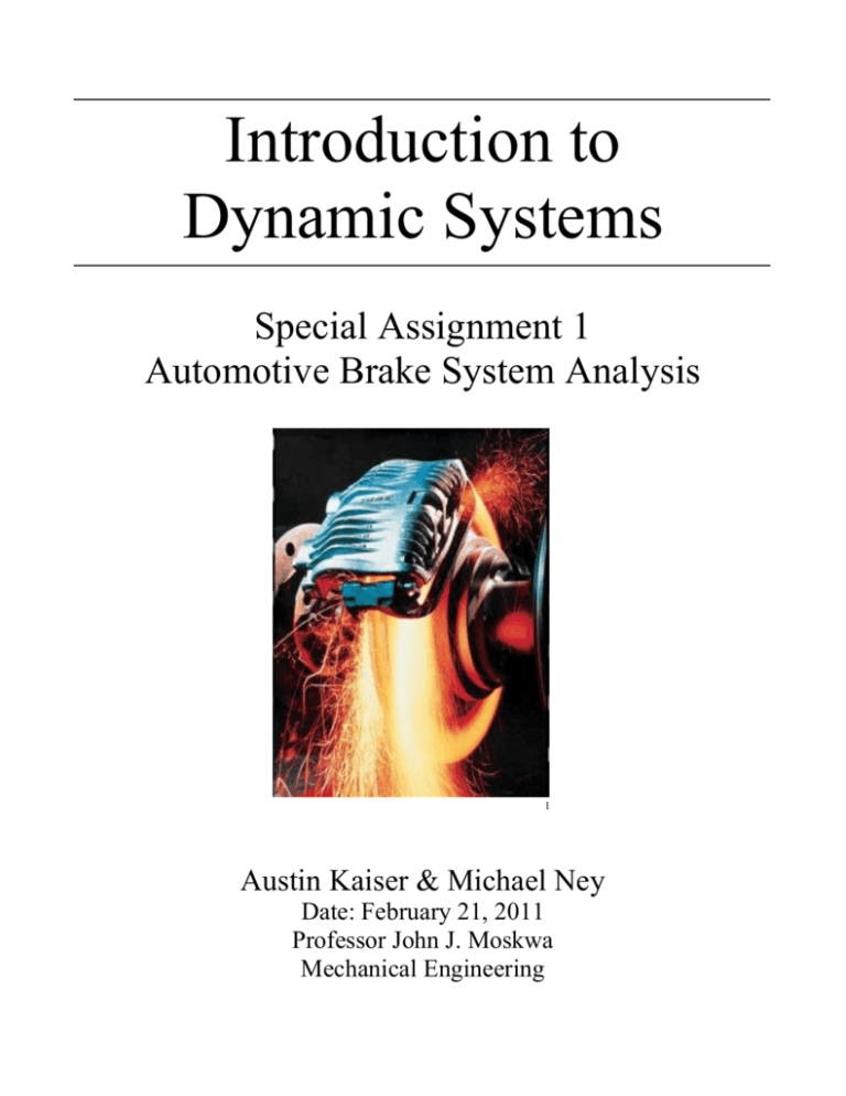
Introduction to Dynamic Systems Special Assignment 1 Automotive Brake System Analysis 1 Austin Kaiser & Michael Ney Date: February 21, 2011 Professor John J. Moskwa Mechanical Engineering Automotive Brake System Analysis The purpose of this project was to analyze the dynamics of an idealized automotive disk brake system in relation to overall vehicle speed. We made various assumptions about the brake system schematic to simplify the free-body diagram and the analysis. Along with studying the physics behind the brake system we also researched and explored it in terms of theoretical and operational analysis. Observations The disk brake system operates with the help of a piston and a caliper. When the brake pedal is activated, a brake pad attached to the piston shifts forward to apply a force to one side of the rotor. The reaction force on the other side of the rotor comes from another brake pad attached to the caliper housing that moves as the piston moves. More pressure on the brake pedal equals more piston and caliper force, and thus faster deceleration of the vehicle.2 Modeling, Free Body Diagrams, and Mathematical Representation We had to make a few assumptions and disregard certain elements of the disk brake system in order to come up with a schematic that we were able to analyze for an idealized model. The assumptions we made to accompany our free-body diagram were: No wear and tear of the brake pads Disc brake system is in perfect alignment The rotor isn’t warped The friction force from the brake pads is constant Neglect static friction forces There is no slip between the road and the tires The same braking force is applied to all four wheels and all components act identically Neglect drag from the air and the road The braking force applied to the pedal is constant, which makes the deceleration constant Included in Appendix A is a schematic of the actual braking system, our free body diagram after assumptions were taken into consideration, and the equations of motion for the idealized system model. Our equation of motion with respect to the wheel and rotor is as follows: 𝐼 𝑑2 𝜃 − 𝑅𝜇𝑘 𝐹𝑁 = 0 𝑑𝜃 2 Where 𝐹𝑁 is the normal force of the brake pad on the rotor, R is the distance from center of rotor to brake pad, 𝜇𝑘 is the coefficient of kinetic friction between the brake pad and rotor, and 𝑑2 𝜃 𝑑𝜃2 is the angular deceleration of the rotating wheel and rotor components. When the driver applies a higher force on the pedal, 𝐹𝑁 will be larger. From this equation, the angular deceleration will have to increase. The angular deceleration of the wheel will result in the car slowing down based on the following equation: ∑ 𝐹𝑥 = 𝑚𝑎 = 𝜇𝑘 𝐹𝑁 − 𝐹𝑎 Where 𝐹𝑁 is the normal force due to the weight of the car, 𝜇𝑘 is the coefficient of kinetic friction between the road and tire, and 𝐹𝑎 is the force of the axle on the tire. The force of the axle has an equal and opposite force on the chassis of the vehicle, thus slowing the entire car down. Analysis We simulated the system by using the driver’s brake pedal force as the input to the system, and the vehicle speed during braking as the output, with it starting at any given coasting speed. Although all four wheels would play a role in an actual vehicle braking maneuver, we simplified the system by only considering the front wheels with no vacuum assist and simplified that even more to a single wheel model. Because we considered constant braking force applied to the system, the result of the analysis was a constant vehicle deceleration. Answers to Specific Questions 1. When the driver depresses the brake pedal he is moving pistons within the vehicle’s master cylinder. The master cylinder contains two pistons in one housing; one for braking the front wheels, and the other for braking the rear.4 Compressing these pistons moves brake fluid through a series of steel and rubber hoses to the car’s caliper system. Brake fluid is incompressible, thus transferring the force from the master cylinder to another piston system in the caliper.3 This system pinches the brake pads on both sides of the rotor together causing a friction force used to decelerate the vehicle. The brake force is increased by using the brake pedal as a lever and controlling the piston sizes in the hydraulic system. 2. After the driver releases the brake pedal, springs in the master cylinder return the pistons back to their original positions. As the pistons return, ports in the cylinders housing are uncovered relieving the pressure that had been built up in the wheel cylinders. A check valve in the system maintains a minimum pressure, thus preventing the entrance of air in the lines.3 When the pressure in the wheel cylinders is relieved, the normal force on the brake pads drops significantly, allowing the pads to ride on the rotor with a very small friction force. 3. Most cars utilize a floating caliper system that allows the caliper to adjust and center itself over the rotor. The floating caliper system uses a single (or sometimes multiple) piston on one side of the rotor to apply the braking force. When brake pressure is applied, the piston in the wheel cylinder pushes the inside brake pad against the rotor.2 The pressure in the cylinder also forces the rigid caliper to slide in its tracks towards the inside of the vehicle. This results in the caliper pushing the outside brake pad against the outside part of the rotor. The final result is both pads pinching the rotor resulting in a braking force. Warped discs cause a much more dynamic system result as a constant pressure on the brake pedal may produce a brake force that isn’t exactly constant. Our model assumes that the rotors are not warped and thus the brake system is aligned perfectly. 4. Since brake systems rely on the incompressibility of the hydraulic brake fluid, introducing air (or any other compressible fluid) can have detrimental effects on the braking reliability and efficiency. Having air bubbles in the system can make the brakes feel spongy.3 This is due to the fact that when the brakes are applied and the pressure in the system increases, the air pockets will compress. This results in less of the brake force being transferred to the wheel cylinder, and thus a less efficient braking system. If air has entered the brake system, it must be bled out to prevent these problems. Conclusions Modeling this system resulted in a dynamic equation where the rotational deceleration of the wheel and rotor were based on the torque caused by the force of friction between the brake pad and rotor. This friction force is a function of the force the driver applies to the pedal. The summation of forces acting on the wheel show that the vehicles velocity decreases as the force of the road on the tire overcomes the force of the axel on the wheel. This project helped us to learn how disc brake systems operate in automobiles and how the dynamic equations we’ve learned about in class can relate to real world applications. We now have a better understanding of how Newton’s laws of motion can be applied to the complex systems we come across every day. References 1. Automotive.com Enthusiast Central: Dialing in Discs. (2011). Retrieved from http://4wheeloffroad.automotive.com/1666/131-0708-4x4-disc-brakes/index.html 2. Bosch automotive handbook. (2007). (7th ed. ed.). Hoboken, N.J. Chichester : Wiley ; John Wiley [distributor]. 3. Marks’ standard handbook for mechanical engineers /(c2007). (11th ed. ed.). New York ; London: McGraw-Hill. 4. How Stuff Works: How Brakes Work. (1998-2011). Retrieved from http://auto.howstuffworks.com/auto-parts/brakes/brake-types/brake3.htm Appendix A Schematic of Braking System 4 Free Body Diagram Equations of Motion ∑ 𝑇 = 𝐼𝛼 𝑑2 𝜃 𝐼 𝑑𝜃2 − 𝑅𝜇𝑘 𝐹𝑁 = 0 𝐹𝑁 = normal force of brake pad on rotor; R=distance from center of rotor to brake pad; 𝜇𝑘 = coefficient of kinetic friction between rotor and brake pad ∑ 𝐹𝑥 = 𝑚𝑎 = 𝜇𝑘 𝐹𝑁 − 𝐹𝑎 𝐹𝑁 = normal force between road and tire; 𝜇𝑘 = coefficient of kinetic friction between road and tire; 𝐹𝑎 = force from axel

