Speedgate Trackless - Specifications 0 MB DOCX
advertisement
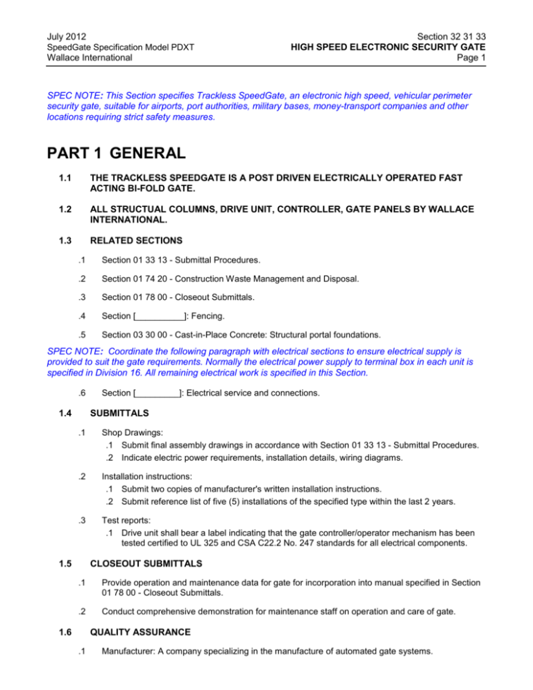
July 2012 SpeedGate Specification Model PDXT Wallace International Section 32 31 33 HIGH SPEED ELECTRONIC SECURITY GATE Page 1 SPEC NOTE: This Section specifies Trackless SpeedGate, an electronic high speed, vehicular perimeter security gate, suitable for airports, port authorities, military bases, money-transport companies and other locations requiring strict safety measures. PART 1 GENERAL 1.1 THE TRACKLESS SPEEDGATE IS A POST DRIVEN ELECTRICALLY OPERATED FAST ACTING BI-FOLD GATE. 1.2 ALL STRUCTUAL COLUMNS, DRIVE UNIT, CONTROLLER, GATE PANELS BY WALLACE INTERNATIONAL. 1.3 RELATED SECTIONS .1 Section 01 33 13 - Submittal Procedures. .2 Section 01 74 20 - Construction Waste Management and Disposal. .3 Section 01 78 00 - Closeout Submittals. .4 Section [__________]: Fencing. .5 Section 03 30 00 - Cast-in-Place Concrete: Structural portal foundations. SPEC NOTE: Coordinate the following paragraph with electrical sections to ensure electrical supply is provided to suit the gate requirements. Normally the electrical power supply to terminal box in each unit is specified in Division 16. All remaining electrical work is specified in this Section. .6 1.4 Section [_________]: Electrical service and connections. SUBMITTALS .1 Shop Drawings: .1 Submit final assembly drawings in accordance with Section 01 33 13 - Submittal Procedures. .2 Indicate electric power requirements, installation details, wiring diagrams. .2 Installation instructions: .1 Submit two copies of manufacturer's written installation instructions. .2 Submit reference list of five (5) installations of the specified type within the last 2 years. .3 Test reports: .1 Drive unit shall bear a label indicating that the gate controller/operator mechanism has been tested certified to UL 325 and CSA C22.2 No. 247 standards for all electrical components. 1.5 CLOSEOUT SUBMITTALS .1 Provide operation and maintenance data for gate for incorporation into manual specified in Section 01 78 00 - Closeout Submittals. .2 Conduct comprehensive demonstration for maintenance staff on operation and care of gate. 1.6 QUALITY ASSURANCE .1 Manufacturer: A company specializing in the manufacture of automated gate systems. July 2012 SpeedGate Specification Model PDXT Wallace International .2 Section 32 31 33 HIGH SPEED ELECTRONIC SECURITY GATE Page 2 Installer: A minimum of three years experience installing similar equipment and approved by manufacturer. PART 2 PRODUCTS 2.1 HIGH SPEED ELECTRONIC SECURITY GATE .1 2.2 Manufacturers: .1 Wallace International Model PDXT SpeedGate Contact Wallace International: 90 Lowson Crescent, Winnipeg, Manitoba Canada, R3P 2H8 T. 866.300.1110 F. 204.284.1868 www.wallaceintl.com MATERIALS .1 Steel sheet: hot dipped galvanized to ASTM A653/A653M, A36 pre galvanized steel. .2 Steel sections: to ASTM (Canadian Equivalent - CAN/CSA-G40.21) Grade [300W] [350W]. .3 Welding materials: to ASWD1.1 (Canadian Equivalent - CSA W59). .4 Electrical components: Complete gate system to be UL325 listed and/or CSA C22.2 No.247 and complying with local requirements. .5 Power Supply: 208/240 V – 20 Amp single phase 60 hertz power supply. 2.3 COMPONENTS .1 Gate Columns: .1 Formed steel columns, anchored to concrete foundation. .2 Columns to be 12” square with a wall thickness of .250”. .2 Model PDXT: .1 Dimensions: [max 8] ft high x [max 24] ft clear opening OR [max 10] ft high x [max 18] ft clear opening. .2 Panels to be capable of fully opening within 7 seconds. .3 Panels: [1.5” vertical bar infill] [6 gauge welded wire infill] [6 gauge woven wire infill]. .4 Manufacturer's standard corrosion resistant hinges. Hinges are to be serviceable heavy duty corrosion resistant base material with a minimum 1 ” stainless steel shaft. .5 Fully compliant with ASTM F2200 – 05, Class I through Class IV. SPEC NOTE: Safety devices are installed to minimize likelihood of vehicle or pedestrian injury/entrapment. Edit the following paragraphs for safety feature options required for project. Pedestrians are NOT permitted to use the automated gate and must be provided with a separate, clearly marked access point. MANUFACTURER’S NOTE: Complete gate system to be UL325 listed and/or CSA C22.2 No.247 and complying with local requirements. .3 Safety/Obstruction Devices: .1 Provide reduced speed sensor - Absolute encoder mounted directly to drive motor to act as primary entrapment detection device. July 2012 Section 32 31 33 HIGH SPEED ELECTRONIC SECURITY GATE Page 3 SpeedGate Specification Model PDXT Wallace International .2 Photoelectric transmitter and receiver: Equip each column with [2] built-in photocells at 20” [and] [60] inches above the base plate. To be mounted within the columns. .3 Provide 2 channel obstruction loop relay card for integration of dual obstruction loops. MANUFACTURER’S NOTE: Control unit to be located within 30 ft. of the gate structure, 2 conduits (recommend 2”) for communication/power cabling to gate structure. Control unit not to be mounted within arm’s reach of the automated gate. .4 2.4 Drive Unit: .1 Provide variable frequency drive with programmable logic controller for controlling electromechanical drive system. Drive system to incorporate encoders with reduced speed sensing software as primary entrapment detection device. .2 All drive electrical components to be enclosed in weather-resistant housing. .3 Dual .75HP 3 Phase gear motors with integrated brake and 360:1 gear reduction box with synthetic lubricant. .4 Emergency override: Provide secured access panel for manual opening and closing in case of power failure/malfunction. FINISHES .1 2.5 Select from: .1 [Hot dip galvanized finish [0.5] kg/m2 zinc coating to ASTM A653/A653M (CAN/CSA-G164)]. .2 [Powder coated to 80 micron thickness - standard RAL colors- check with manufacturer before specifying color] . PRODUCT OPTIONS .1 .2 .3 .4 [Anti climb top guard] [Red / Green traffic lights][For Entrance][For Exit]. [Fence Mounting Devices: Provide mounting brackets for mounting adjoining fence material to columns]. [UPS Backup: Provide Uninterruptible Power Supply to variable speed gate controller for emergency operation in event of power outages]. PART 3 EXECUTION 3.1 INSTALLATION .1 Provision of concrete foundations as determined by local engineer according to drawings provided. .2 Install high-speed security gate to manufacturer's written instructions, by contractor certified by Wallace International. .3 Submit certificate of installation to manufacturer upon completion of installation for warranty validation 3.2 CLEANING AND MAINTENANCE .1 Perform cleaning and maintenance procedures in strict accordance with manufacturer’s written instructions. .2 Maintain logbook of repairs and maintenance. END OF SECTION
