Slide 1
advertisement

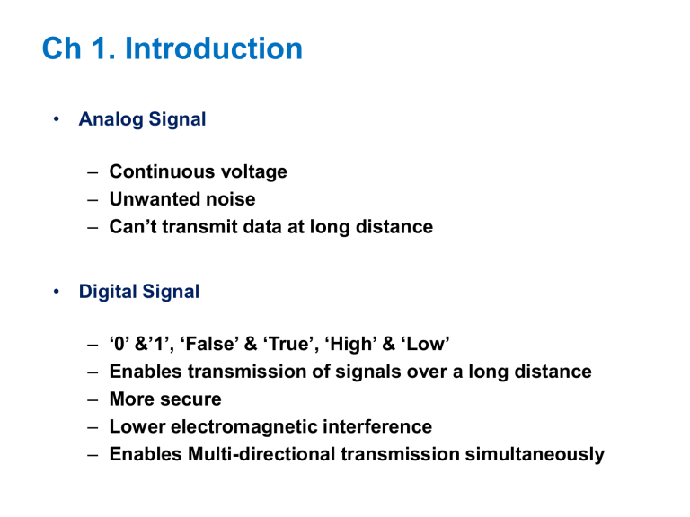
Ch 1. Introduction • Analog Signal – Continuous voltage – Unwanted noise – Can’t transmit data at long distance • Digital Signal – – – – – ‘0’ &’1’, ‘False’ & ‘True’, ‘High’ & ‘Low’ Enables transmission of signals over a long distance More secure Lower electromagnetic interference Enables Multi-directional transmission simultaneously 1.3 Digital Devices • Gate – The most basic digital devices – Got there name from their function (AND, OR…) – Gate has one or more inputs and produces output that is function of current input values INPUT 2 input AND gate OUTPUT A B Y 0 0 0 0 1 0 1 0 0 1 1 1 INPUT 2 input OR gate OUTPUT A B Y 0 0 0 0 1 1 1 0 1 1 1 1 1.4 Electronic Aspects of Digital Design Logic Function Electronic Function • Noise Margin – The voltage difference between the guaranteed output level and the required input voltage of a logic gate – In a real circuit, a gate’s output can be corrupted by this much noise 1.5 Software Aspects of Digital Design Software Tools CAD Schematic Diagram HDLs Text editors Compilers Synthesizers Simulators Test Benches Timing Analyzers Ex) Modelsim, Xilinx, Synplify, XST • HDL - Hardware Description Language - 1980년대 초부터 미 국방성에서 사용시작 - 1981년 VHDL (VHSIC Hardware Description Language) 제안, 이후 IEEE 표준으로 채택 • HDL 이전 - Layout editor나 Schematic editor를 사용 - 작은 블록을 설계하고 큰 블록을 설계하는 Bottom-up 방식 - 회로의 규모가 커지고 복잡도가 증가함에 따라 한계 발생 • HDL 이후 - 알고리즘이나 기능 레벨에서 설계가 가능 - Top-down 방식 - 복잡한 회로의 설계 가능 1.6 Integrated Circuits • IC (Integrated Circuit) – Collection of one or more gates fabricated on a single silicon chip – SSI (Small Scale IC) →MSI (Medium Scale IC) →LSI (Large Scale IC) → VLSI (Very Large Scale IC)→SoC (System on Chip) → NoC (Network on Chip) – pad, die Pin diagrams are used only for mechanical reference 1.7 Programmable Logic Devices PLA (Programmable logic array) : Only two level structure (AND, OR) PAL (Programmable array logic), PLD(Programmable logic device) →CPLD(Complex PLD)→FPGA(Field-programmable gate array) 1.10 Digital-Design Levels input 𝐖𝐡𝐞𝐧 𝑺 = 𝟎, 𝒁 = 𝑨 𝐖𝐡𝐞𝐧 𝑺 = 𝟏, 𝒁 = 𝑩 output Turn on when ‘0’ output input 𝒔 Turn on when ‘1’ 𝐖𝐡𝐞𝐧 𝑺 = 𝟎, 𝒁 = 𝑨 𝐖𝐡𝐞𝐧 𝑺 = 𝟏, 𝒁 = 𝑩 2-input 4-bit MUX Input : A and B (0~4bits) Output : Z (0~4bits) 𝐖𝐡𝐞𝐧 𝑺 = 𝟎, 𝒁 = 𝑨 𝐖𝐡𝐞𝐧 𝑺 = 𝟏, 𝒁 = 𝑩 𝐖𝐡𝐞𝐧 𝑺 = 𝟎, 𝒁 = 𝑨 𝐖𝐡𝐞𝐧 𝑺 = 𝟏, 𝒁 = 𝑩 Conditional operator 𝒁 = 𝐂𝐨𝐧𝐝𝐢𝐭𝐢𝐨𝐧 ? 𝐓𝐫𝐮𝐞: 𝐅𝐚𝐥𝐬𝐞


