Analysis of Wake Flows for Induced Drag Reduction
Analysis of Wake Flows for Induced Drag Reduction
M.C. Jones
1
and K.D.Visser
2
Department of Mechanical and Aeronautical Engineering
In the world today, many aircraft are put to the test before they even reach a wind tunnel. They are analyzed using Computational Fluid Dynamics (CFD). These CFD analyzers allow a large number of designs to be tested before running them through a wind tunnel. The present study involves finding a way to extract more data from the CFD analysis and then to use this method to analyze the wake flows of induced drag reducing wing designs.
The first part of the research involves determining the best method for analyzing CFD results. This involves taking a slice of the wake flow of a swept wing and then running that slice data through an analyzer to extract data. Because of this, it was decided to look at three specific areas to optimize: the distance between the wing and the slice, the density of the slice grid, and the angle of the slice.
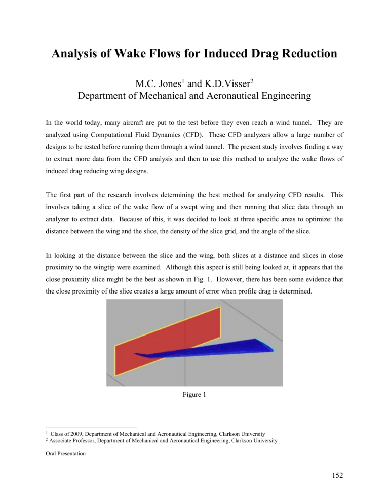
In looking at the distance between the slice and the wing, both slices at a distance and slices in close proximity to the wingtip were examined. Although this aspect is still being looked at, it appears that the close proximity slice might be the best as shown in Fig. 1. However, there has been some evidence that the close proximity of the slice creates a large amount of error when profile drag is determined.
Figure 1
1 Class of 2009, Department of Mechanical and Aeronautical Engineering, Clarkson University
2 Associate Professor, Department of Mechanical and Aeronautical Engineering, Clarkson University
Oral Presentation
152
The density of the slice grid is a very important part of the CFD analysis. In order to run a slice through the analyzer, it must be interpolated onto an orthogonal grid. The problem here is getting the grid density dense enough so that there is no loss in definition but not too dense so as to require inordinate amounts of computing time. It appears that the most accurate grid size is 1 mm 2 or less as shown in Fig. 2. Although a grid size of less than 1 mm 2 may be more accurate, it does add a significant amount of computation time.
Figure 2
Finally, slice angle is the angle at which the slice is taken. In looking at slice angles, it is necessary to examine how much error is created by taking the slice perpendicular to the angle of attack rather than the flow angle, as this requires more computation time. Also, slices parallel to the trailing edge of the wing rather than perpendicular to the flow field were tested. Although this has not been fully investigated, it could help in deciding on an optimal grid density.
Once the optimal CFD analysis method has been determined, a number of wings testing drag-reducing wingtip designs will be tested. These wingtip designs, which were generated by David Maragno, a graduate student at Clarkson University, test various sweep and dihedral angles on the tips. From these results, the optimal tip design can be determined.
153

