draft NEW SHIP DESIGN INDEX
advertisement
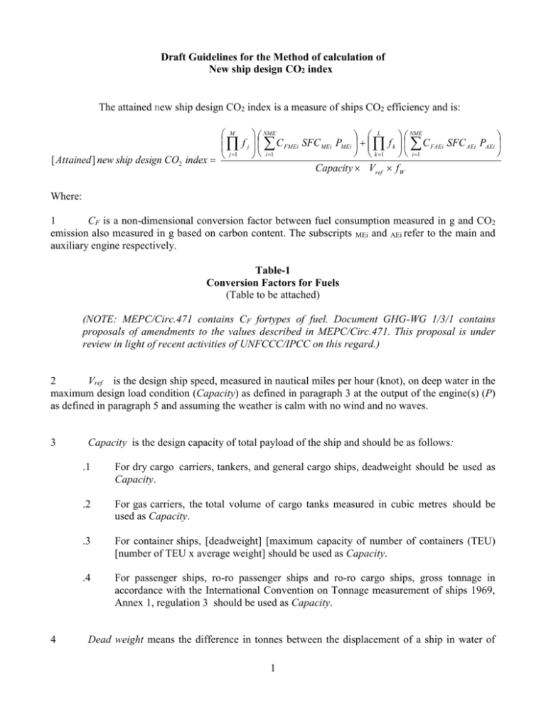
Draft Guidelines for the Method of calculation of New ship design CO2 index The attained new ship design CO2 index is a measure of ships CO2 efficiency and is: M NME NME L f j C FMEi SFC MEi PMEi f k C FAEi SFC AEi PAEi i 1 j 1 k 1 i 1 [ Attained ] new ship design CO2 index Capacity Vref f W Where: 1 CF is a non-dimensional conversion factor between fuel consumption measured in g and CO2 emission also measured in g based on carbon content. The subscripts MEi and AEi refer to the main and auxiliary engine respectively. Table-1 Conversion Factors for Fuels (Table to be attached) (NOTE: MEPC/Circ.471 contains CF fortypes of fuel. Document GHG-WG 1/3/1 contains proposals of amendments to the values described in MEPC/Circ.471. This proposal is under review in light of recent activities of UNFCCC/IPCC on this regard.) 2 Vref is the design ship speed, measured in nautical miles per hour (knot), on deep water in the maximum design load condition (Capacity) as defined in paragraph 3 at the output of the engine(s) (P) as defined in paragraph 5 and assuming the weather is calm with no wind and no waves. 3 4 Capacity is the design capacity of total payload of the ship and should be as follows: .1 For dry cargo carriers, tankers, and general cargo ships, deadweight should be used as Capacity. .2 For gas carriers, the total volume of cargo tanks measured in cubic metres should be used as Capacity. .3 For container ships, [deadweight] [maximum capacity of number of containers (TEU) [number of TEU x average weight] should be used as Capacity. .4 For passenger ships, ro-ro passenger ships and ro-ro cargo ships, gross tonnage in accordance with the International Convention on Tonnage measurement of ships 1969, Annex 1, regulation 3 should be used as Capacity. Dead weight means the difference in tonnes between the displacement of a ship in water of 1 relative density of 1.025 at the load waterline corresponding to the assigned summer freeboard and the lightweight of the ship. 5 P is the designed power of the main and auxiliary engines, measured in kW. The subscripts ME and AE refer to main and auxiliary engine, respectively. The summation on i is for all engines with the number of main engines (NME) and the number of auxiliary engines (NAE). .1.1 PME is the required main engine power to obtain the design speed (Vref) under the loading condition of Capacity.; .1.2 For engine-generator + electric motor driven propulsion system, PME is the power required from the generator engines to obtain the same condition as per .1.1.; .2 PAE is the required auxiliary engine power to supply normal maximum sea load including necessary power for machinery, systems, equipment and living on board in the condition where the ship engaged in voyage at the design speed (Vref) under the design loading condition of Capacity. Required fuel consumption for boiler(s) should also be included as one of PAEi, where any steam generated is not obtained from the exhaust gas. 6 Vref, Capacity, and P should be consistent each other, and should represent the designed sea-going condition of the ship [in a calm sea condition]. 7 SFC is the [designed] specific fuel consumption, measured in g/kWh, of the engines at the power output of P determined by paragraph 5. The subscripts MEi and AEi refer to the main and auxiliary engine respectively, including boilers as appropriate. 8 fj and fk are corrections to account for ship specific design elements [such as, e.g., ice strengthening, cargo gear or reefer containers]. fj and fk refer to main and auxiliary engine respectively. (NOTE: Method for determination of fj and fk shall be prepared and prescribed in this document.) 9 fW is a non-dimensional coefficient indicating the decrease of speed in representative sea conditions of wave height, wave frequency and wind speed (e.g., Beaufort Scale 6), and should be determined as follows: .1 It can be determined by conducting the ship-specific simulation of its performance at representative sea conditions. The simulation methodology shall be prescribed in the Guidelines developed by the Organization and the method and outcome for an individual ship shall be verified by the Administration or an organization recognized by the Administration. .2 In case that the simulation is not conducted, fW value should be taken from the “standard 2 fW ” table/curve. “Standard fW ” table/curve, which is to be contained in the Guidelines, is given by ship type (the same ship as the “baseline” below), and expressed in a function of the parameter of Capacity (e.g., DWT).. “Standard fW ” table/curve is to be determined by conservative approach, i.e., based on the data of actual speed reduction of as many existing ships as possible under the representative sea conditions. Table-2 standard fW ” table/curve (Table or curve to be attached) (NOTE: If “standard fW ” table/curve or simulation methodology is not provided in this document , fW can be assumed [one (1)] [0.9] until such table/curve is given.) *** 3

