ORGANIC CONTAMINATION OF STEAM SYSTEM
advertisement
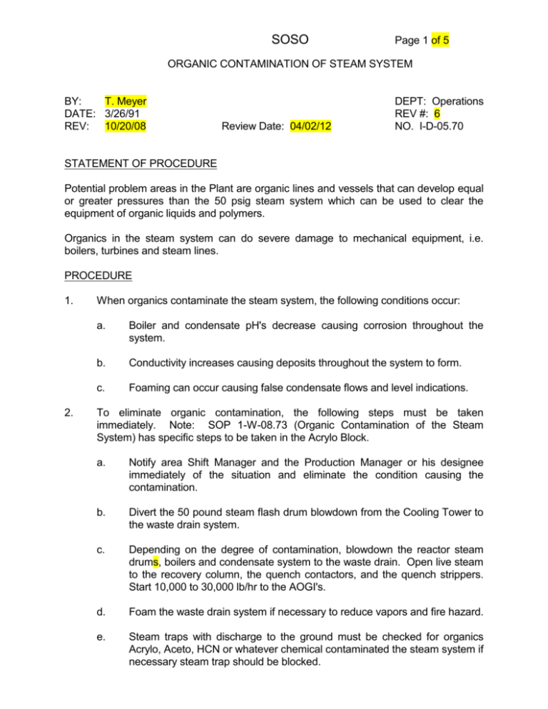
SOSO Page 1 of 5 ORGANIC CONTAMINATION OF STEAM SYSTEM BY: T. Meyer DATE: 3/26/91 REV: 10/20/08 Review Date: 04/02/12 DEPT: Operations REV #: 6 NO. I-D-05.70 STATEMENT OF PROCEDURE Potential problem areas in the Plant are organic lines and vessels that can develop equal or greater pressures than the 50 psig steam system which can be used to clear the equipment of organic liquids and polymers. Organics in the steam system can do severe damage to mechanical equipment, i.e. boilers, turbines and steam lines. PROCEDURE 1. 2. When organics contaminate the steam system, the following conditions occur: a. Boiler and condensate pH's decrease causing corrosion throughout the system. b. Conductivity increases causing deposits throughout the system to form. c. Foaming can occur causing false condensate flows and level indications. To eliminate organic contamination, the following steps must be taken immediately. Note: SOP 1-W-08.73 (Organic Contamination of the Steam System) has specific steps to be taken in the Acrylo Block. a. Notify area Shift Manager and the Production Manager or his designee immediately of the situation and eliminate the condition causing the contamination. b. Divert the 50 pound steam flash drum blowdown from the Cooling Tower to the waste drain system. c. Depending on the degree of contamination, blowdown the reactor steam drums, boilers and condensate system to the waste drain. Open live steam to the recovery column, the quench contactors, and the quench strippers. Start 10,000 to 30,000 lb/hr to the AOGI's. d. Foam the waste drain system if necessary to reduce vapors and fire hazard. e. Steam traps with discharge to the ground must be checked for organics Acrylo, Aceto, HCN or whatever chemical contaminated the steam system if necessary steam trap should be blocked. I-D-05.70 SOSO f. Consideration must be given to cancel Hot Work Permit to reduce the fire hazard. (Sound Alarm) g. Make a map (drawing) indicating the affected area(s) and develop a plan to continue to check these areas until it is considered "safe". **NOTE: 3. B, C, & D are needed to minimize and/or eliminate atmospheric contamination. DO NOT BLOWDOWN TO THE DITCH. To prevent steam contamination, one must consider the operational equipment needing use of the steam system other than NORMAL operation. a. Do not connect steam out lines to any equipment having higher or equal pressure which is in service such as closed vessels and pump discharge lines. b. Vessels requiring steamout must be depressured and properly vented to the process flare or the chemical drain prior to steaming. c. Pump discharge lines needing steaming must be isolated and depressured to the chemical drain prior to steaming. Some of the common pumps having equal or greater pressure than the 50 pound steam system in the Acrylonitrile unit, Acetone Cyanohydrin unit, and Aceto Purification unit are listed on the following pages. This list is not all inclusive and prior to connecting to any equipment not listed thought must be given to the pressure and service involved. ACRYLONITRILE UNIT PUMPS I. Page 2 of 5 Rev: # 6 Pump No. Disch. Pres. GA-102/S GA-202/S GA-3003/S 150 psig 150 psig 150 psig GA-103/S GA-203/S GA-3004/S GA-4004/S 160 psig 160 psig 160 psig 160 psig Reactor Areas A. Process Condensate 1. 2. 3. B. #1 Train #2 Train #3 Train Rich Water (to Recovery) 1. 2. 3. 4. #1 Train #2 Train #3 Train #4 Train I-D-05.70 C. SOSO GA-101/S GA-201/S GA-3002/S GA-4002/S 50 psig 50 psig 50 psig 50 psig #1 Train #2 Train #3 Train #4 Train GA-104 A,B,C GA-204 A,B,C GA-3001 A,B,C GA-4001A,B,C 70 psig 70 psig 70 psig 70 psig #3 Train #4 Train GA-3005/S GA-4005/S 80 psig 80 psig GA-403/S GA-405/S 120 psig 280 psig GA-406/S GA-407/S 130 psig 50 psig GA-408/S GA-409/S 75 psig 60 psig GA-501/S 70 psig GA-502/S GA-519 80 psig 125 psig RECOVERY AREA A. Recovery Column 1. 2. B. C. Recovery Column Btms Lean Water Surge Drum Recovery Column Decanter 1. 2. Water Boot Side Organic Side Aceto Fractionator 1. 2. III. #1 Train #2 Train #3 Train #4 Train Absorber Side System 1. 2. II. Disch Pres. High Volume Recirculation 1. 2. 3. 4. E. Pump No. Stripper Bottoms 1. 2. 3. 4. D. Page 3 of 5 Rev: # 6 Bottoms Reflux Purification Area A. Heads Column Bottom B. Product Column 1. 2. Product Col. Bottoms Product Col. Vacuum Pot I-D-05.70 C. SOSO E. Disc. Pres Water Boot Side Organic Side GA-504 GA-505/S 140 psig 50 psig Aceto Heads Column (A/H) Area 1. 2. A/H Column Bottoms Aceto Side Draw GA-415X&SX GA-416X&SX 130 psig 140 psig 3. Overhead Condenser GA-417X&SX 150 psig GA-506/S GA-603 GA-602S 50 psig 110 psig 150 psig Acrylo Rundown Tank Area 1. 2. 3. F. Pump No. Purification Decanter 1. 2. D. Page 4 of 5 Rev: # 6 Acrylo Transfer Slop Water Waste Drain Chemical Additives *Positive displacement pumps are capable of very high discharge pressures 1. 2. 3. HQ (Heads Col.) (Recovery Col.) (Aceto Heads Col.) MEHQ (Prod Col.) (Rndn Tanks) Glycolic Acid (Heads Col.) (Aceto Heads Col.) GA-507 GA-507S GA-510&B GA-509&S GA-508 Variable " " " " " " " " GA-510&S GA-517 " " " " GA-804/S 70 psig GA-806/S 75 psig GA-808/S GA-810/S GA-809/S 70 psig 50 psig 70 psig ACETONE CYANOHYDRIN UNIT A. Generator Circ. Pumps B. Dilute Filter Feed Pumps C. 1st Stage Pumps 1. 2. 3. Feed Pump Hotwell Cond. Pump Bottoms Pumps I-D-05.70 D. SOSO Page 5 of 5 Rev: # 6 Pump No. Disc. Pres. GA-812/S GA-814/S 50 psig 55 psig 2nd Stage Pumps 1. 2. Feed Pumps Bottoms Pumps E. HCN Refrig. Compressor 175 psig F. Acetone Flush Pumps (Positive Disp.) Variable G. All Pumps in the Aceto Unit. - Crude Rerun Pumps

