Application of Control Volume Energy Analysis
advertisement
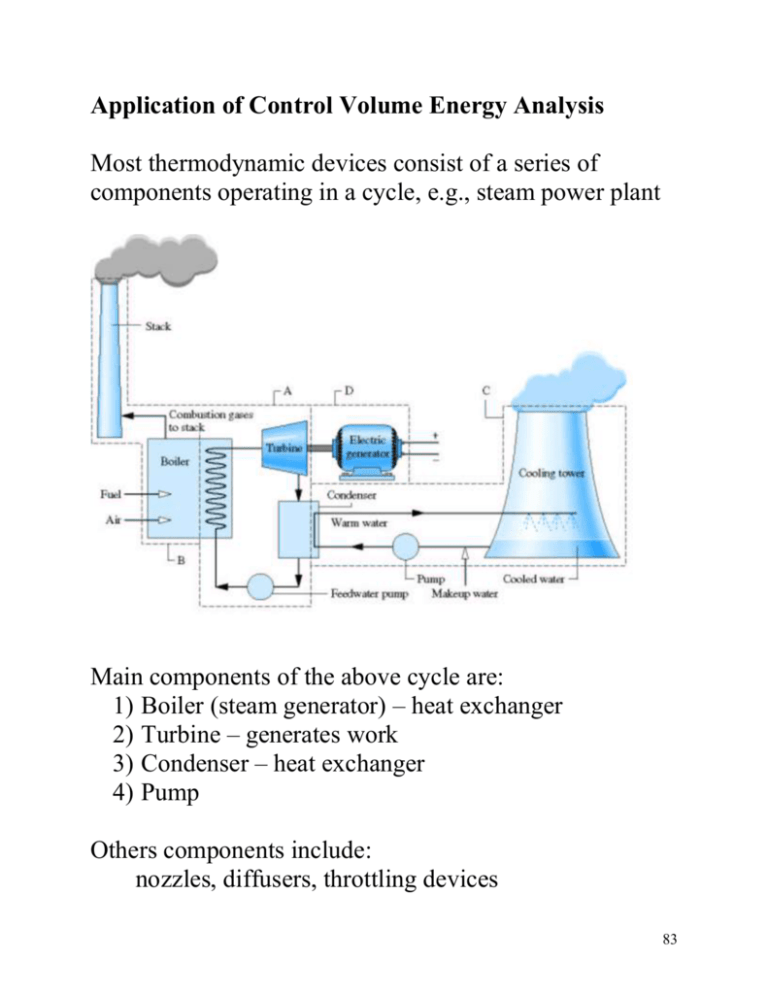
Application of Control Volume Energy Analysis Most thermodynamic devices consist of a series of components operating in a cycle, e.g., steam power plant Main components of the above cycle are: 1) Boiler (steam generator) – heat exchanger 2) Turbine – generates work 3) Condenser – heat exchanger 4) Pump Others components include: nozzles, diffusers, throttling devices 83 Nozzles and Diffusers Devices that increase or decrease the flow velocity by passing the flow through a variable area duct, A1 A2 1 2 Applying conservation of mass assuming steady flow: dM CV 1 A1V1 2 A2V2 dt 1 A1V1 2 A2V For low subsonic flow (1 = 2) V2 A1 V1 A2 84 Subsonic Nozzle: A2 < A1 V2 > V1 Subsonic Diffuser: A2 > A1 V2 < V1 Aircraft gas turbine diffuser nozzle Applying the energy equation (assuming steady, no heat loss, PE=0): dE q w s (hi Vi 2 / 2 gZ i ) (he Ve2 / 2 gZ e ) 0 dt h1 V12 / 2 h2 V22 / 2 V22 V12 2(h1 h2 ) For a rocket nozzle V2 >> V1 V22 2(h1 h2 ) 85 Turbine A device in which shaft work is generated as a result of gas passing through a set of blades attached to a freely rotating shaft The rotating blades redirect the flow off axis, so you need a set of fixed blades that straighten out the flow before the next set of rotating blades Rotating blades Fixed blades Rotating blades 86 In this course we are not interested in the details of the flow through each blade, or row of blades. We are interested in the overall energy balance W 1 Flow T 2 Applying First Law (steady-state, neglect heat transfer) 0 q w (h1 V12 2) (h2 V22 2) w (h1 h2 ) (V12 2 V22 2) work per unit mass Often the change in KE is small compared to change in h i.e., h1 h2 V12 2 V22 2 w h1 h2 Note: work output ( w 0) h1 h2 Power is work output per unit time m w m (h1 h2 ) W 87 EXAMPLE Steam enters a turbine operating at steady-state with a mass flow rate of 4600 kg/h. The turbine develops a power output of 1000 kW. At the inlet the pressure is 60 bars, the temperature is 400C and the velocity is 10 m/s. At the exit the pressure is 0.1 bar, the quality is 0.9 and the velocity is 50 m/s. Calculate the rate of heat transfer between the turbine and the surroundings, in kW. steam m = 4600 kg/hr P1= 60 bar T1= 400C V1= 10 m/s 1 W T liquid/vapor x2= 0.9 P2= 0.1 bar V2= 50 m/s 2 T 400C 276C 60 bar 1 0.1 bar 2 v 88 Assume steady-state and PE is negligible 0 q w (h1 V12 2) (h2 V22 2) q w (h2 h1 ) (V22 2 V12 2) Need enthalpy at states 1 and 2 State 1: From saturated water Table A-3 Tsat (60 bar)= 275.6C since T1>Tsat at same pressure have superheated vapor From superheated water vapor Table A-4 h(60bar, 400C)= 3177.2 kJ/kg State 2: From saturated water Table A-3 hf(0.1 bar)= 191.8 kJ/kg hg(0.1 bar)= 2584.7 kJ/kg h2= hf + x2(hg-hf) = 191.8 + 0.9(2392.8)= 2345.4 kJ/kg so h2- h1= 2345.4 - 3177.2 = -833.8 kJ/kg 89 0.5V22 V12 = 0.5(502 - 102 ) = 1200 m 2 /s 2 m 2 1 N 1 J J 1200 2 1200 kg s kg m/s 2 N m Collecting terms: q w (h2 h1 ) (V22 2 V12 2) Q W m (h2 h1 ) m (V22 2 V12 2) 1000 kW 4600 kg 1 hr kJ kJ 833.8 1.2 hr 3600 s kg kg Q 61.3 kW Negative sign implies heat loss from turbine Note: 1) Difference in magnitude between h and ke 2) Magnitude of heat loss Q (61 kW) compared to magnitude of power output W (1000 kW) 90 Compressor/pump A device in which shaft work input is used to raise the pressure of a fluid (liquid or vapor) 91 Again we are not interested in the details of the flow through each blade or row of blades. We are interested in the overall energy balance Flow 1 W C 2 Applying First Law (steady-state, neglect heat transfer and PE) 0 q w (h1 V12 2) (h2 V22 2) w (h1 h2 ) (V12 2 V22 2) work per unit mass Often the change in KE is small compared to change in h i.e., h1 h2 V12 2 V22 2 w h1 h2 Note: work input ( w 0) h2 h1 92 Throttling Device A device that generates a significant pressure drop via a flow restriction, e.g., partially closed valve. 1 2 Applying First Law (steady-state, neglect heat transfer and PE) 0 q w (h1 V12 2) (h2 V22 2) h1 V12 / 2 h2 V22 2 If the state 2 is taken far downstream from the blockage the change in velocity is negligible, i.e., V1 V2 h1 h2 Throttling process is characterized by constant enthalpy 93 Heat Exchangers These are devices that transfer energy between fluid streams at different temperatures cool or heat one of the fluids. The following is a tube-in-tube heat exchanger 4 2 1 3 Can have cross-flow or parallel-low type Applying First law to above cross flow heat exchanger assuming steady flow, no heat loss to the environment and KE and PE is negligible 0 Q W m 1 (h1 V12 2 gZ1 ) m 3 (h3 V32 2 gZ 3 ) m 2 (h2 V22 2 gZ 2 ) m 4 (h4 V42 2 gZ 4 ) Steady flow so m 1 m 2 and m 3 m 4 0m 1 (h1 h2 ) m 3 (h3 h4 ) 94 Solving we get m 1 h4 h3 m 3 h1 h2 To get the rate of heat transfer from one stream to the other perform CV analysis on only the inner-tube (assume inner-stream is hotter than outer-stream) Qi 2 1 Again Applying First Law with same assumptions 0 (Q i ) m 1 (h1 h2 ) Q i (h1 h2 ) m 1 Since Q i 0 h1 h2 , so T1 > T2 (fluid cools down) 95 A CV analysis of the outer-stream would give 4 3 Qo 0 (Q o ) m 3 (h3 h4 ) Q o (h4 h3 ) m 3 Since Q o 0 h4 h3 , so T4 > T3 (fluid heats up) Note, the magnitude of the energy transfer rate from the inner stream Q i equals the magnitude of the energy transfer rate into the outer-stream Q o Q i Q o m 1 h1 h2 m 3 h4 h3 m 1 h4 h3 m 3 h1 h2 Note we recover the same relationship obtained using the global energy balance 96 Another common type of heat exchanger is a direct contact heat exchanger, e.g., open feed water heater. Hot stream, m 1 Warm stream, m 3 Cold stream, m 2 This type of heat exchanger consists of a vessel where a hot stream and cold stream of the same fluid are mixed and exit at an intermediate temperature through a single outlet. Apply conservation of mass and First Law to the CV and assuming steady state, negligible KE and PE change to get: dM CV m 1 m 2 m 3 dt 0m 1 m 2 m 3 dECV Q W m 1 (h1 ) m 2 (h2 ) m 3 (h3 ) dt 0m 1h1 m 2 h2 m 3 h3 97 Transient Control Volume Analysis Applies when the CV has only one inlet or one exit Reservoir: constant T constant P valve CV Considering the filling of a rigid tank of volume Vcv with a gas supplied at a constant pressure and temperature Applying conservation of mass dM CV m i m e dt Applying First Law, neglecting heat transfer to environment, KE and PE dECV dU CV Q W m i (hi Vi 2 / 2 gZ i ) m e (.....) dt dt 98 Note: constant enthalpy across the valve (throttling device) gas specific enthalpy, hi , into the CV equals the gas specific enthalpy in the reservoir, hR dU CV m i hi m i hR dt Substituting dU CV dM CV hR dt dt Integrating from the initial state " i" to the final state " f" Uf Mf Ui Mi dU hR dM U f U i ( M f M i ) hR M f u f M i u i ( M f M i ) hR 99 If the tank is initially empty (vacuum) mi = 0 M f u f M f hR cV T f c PTR Tf cP TR kTR cV Work done getting gas into the CV results in a final tank gas temperature higher than the reservoir temperature 100
