design and build of the waste water treatment plant and ancillary
DESIGN AND BUILD OF THE WASTE WATER TREATMENT PLANT AND ANCILLARY FACILITIES
IN ROUSSE
EMPLOYER
MINISTRY OF REGIONAL DEVELOPMENT AND PUBLIC WORKS
ISPA IMPLEMENTING AGENCY – MEASURE 2005/BG/16/P/PE/004
BENEFICIARIES
REGIONAL WATER COMPANY OF ROUSSE
MUNICIPALITY OF ROUSSE
CONSULTANT
JV POYRY ENVIRONMENTAL AND CONSULTING ENGINEERING GROUP
CONTRACTOR
HOCHTIEF CONSTRUCTION AG
1: OVERVIEW
As one of the European Union Countries, Bulgaria is obliged to comply with the standards and requirements of the European Union. This leads to the reconstruction and upgrading of the Country’s infrastructure including sewerage networks and wastewater treatment plants.
In 2005 the European Union and the Republic of Bulgaria signed the Financing
Memorandum for the Integrated Water Project in Rousse, including a component for the Design and Build of the Waste Water Treatment Plant and Ancillary Facilities.
2: PROJECT BACKGROUND
The Rousse Municipality has a current population of around 160,000 inhabitants. It is an active industrial centre with a harbour of the Danube River.
The Project is co-financed with ISPA Funding and Bulgarian Government contributions at a total budget cost of EUR 22,857,429.
The construction of the Waste Water Treatment Plant is consistent with the National
Programme for Priority Construction of Urban Waste Water Treatment Plants of populated areas with over 10,000 inhabitants.
3: PROJECT OBJECTIVES
The overall objectives of the Project are to improve the quality of the services provided by the Regional Water Company to the population, to improve the efficiency of the use of water resources in accordance with the principles laid down in the
European Water Framework Directive and to achieve compliance with the European
Directive on Urban Waste Water Treatment by the target date of 31 December 2010.
Overall, the Project will treat the domestic, commercial and industrial effluents of a region with a projected population by the year 2030 of around 240,000. The city of
Rousse has an extensive network of sewage collection but no wastewater treatment facilities.
JV P öyry Envirionment GmbH/Consulting Engineering Group
4: PROJECT COMPONENTS
The scope of works is the design and construction of the Waste Water Treatment
Plant based on the preliminary design provided by the Contracting Authority together with the supervision, operation and maintenance and the additional design and construction of the ancillary facilities to the sewerage network.
The key areas of work are as follows:
Detailed Design of the Wastewater Treatment Plant (WWTP) for a 240,000 population equivalent;
Construction of the WWTP to perform an adequate treatment of discharge final effluent to the Danube River;
Design and construction of two Wastewater Pumping Stations;
Design and construction of Sewerage Collectors of total length 4km comprising of
2.3 km of diameter 1600mm gravity Collector and 1.7 km of diameter 1200mm pumping Collector to the WWTP;
Supervision of the design, construction, operation and maintenance with Training monitoring of the Operational personnel.
The selected site is very close to the Danube River and the site preparation works will include the necessary flood protection works.
The treated wastewater has been designed to meet the requirements of the Urban
Wastewater Directive 91/271/EEC of 21 May 1991.
5: WASTE WATER TREATMENT PROCESS
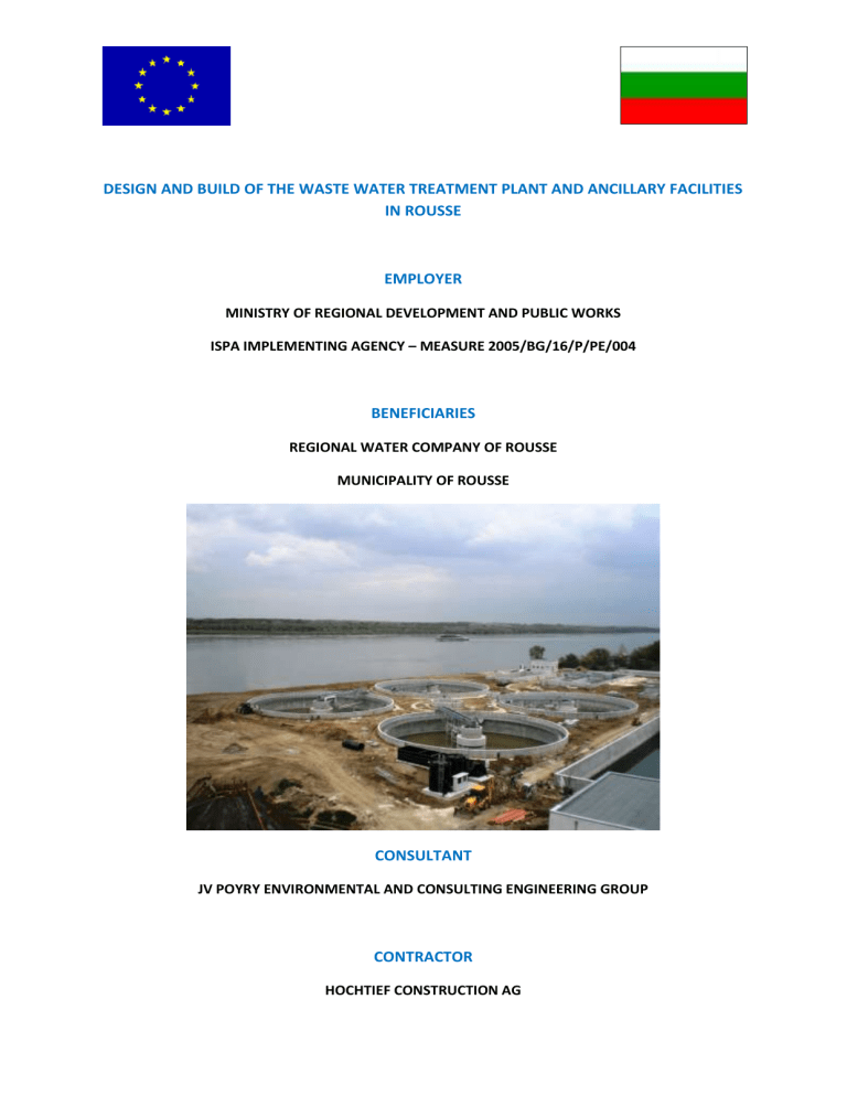
The site of the WWTP is situated in the East Industrial Zone of Rousse on the banks of the Danube River.
The site of the WWTP occupies around 35,000 dka (35 ha). The site has been levelled to around 22.4 m which is around 2.0 m above the maximum water level of the Danube River as determined by the Ministry of Transportation and
Communications.
The key elements of the treatment process comprise of:
INLET WORKS.
Receiving channel with flow measurement for the sewage from the constructed Town Collectors
SCREEN BUILDING.
Comprises of fine screens which transport the screened material by spiral conveyor to hoppers.
JV P öyry Envirionment GmbH/Consulting Engineering Group
GRIT AND GREASE CHAMBER
. After passing the Screen Building, the sewage reaches the aerated Grit and Grease Chamber. The grit and sands are separated by diffused aeration by keeping the organic substances suspended. The grit is removed by scrapers and conveyed to Grit Classifiers from which the sand is removed to adjacent containers.
PRIMARY SETTLING TANKS.
Wastewater from the Grit and Grease
Chamber is fed into a distribution channel and into two Settlement Tanks to take-out the primary sludge. The Tanks are fitted with scraper bridges and floating sludge collecting system. The sludge is delivered to hoppers and transported to the primary sludge pumping station. The floating scum is discharged to the scum Pumping Station.
BIOLOGICAL TREATMENT.
This comprises of Aeration Tanks and
Secondary Settlement Tanks. The Aeration Tanks introduce diffused air at the base of the tanks which produced further suspended solids in the form of micro-organisms that remove carbon and phosphorus as well as the nitrogen compounds known as nitrification. Wastewater from the Aeration tanks flow to the Secondary Settlement Tanks where the settlement of the biological sludge and the clarified final clear effluent take place. The settled sludge is conveyed back to the inlet of the Aeration Tanks.
CHLORINATION TANK.
Clear effluent from the Secondary Settlement
Tanks is conveyed to the Chlorination Tank from which the final effluent passes to the Danube River. Disinfection by chlorination is provided as an emergency measure only.
SLUDGE TREATMENT.
The sludge left after the various treatment processes is passed to the Technical Building where it is mechanically thickened before it is conveyed to the Digesters. In the Digesters the sludge is processed under high temperatures until methane is produced for small scale electricity and heating requirements. Excess gas is conveyed to the Gas Flare where it is burnt off. Excreted sludge from the Digester process is taken back to the Technical building for dewatering and then stored in the Sludge
Storage Area for removal off site.
JV P öyry Envirionment GmbH/Consulting Engineering Group
6: PROGRAMME OF WORKS
Date of Commencement
Date of Take Over
30 January 2008
17 December 2010
7: CURRENT PROGRESS
Civil Works
Mechanical / Electrical
Pumping Stations and Collectors
92%
72%
3%
JV P öyry Envirionment GmbH/Consulting Engineering Group

