Phys 184 lab 9 diffr
Phys 184
DIFFRACTION
Object:
To investigate the diffraction and interference of light,
Apparatus:
Lasers, metersticks, single and double slits.
Theory:
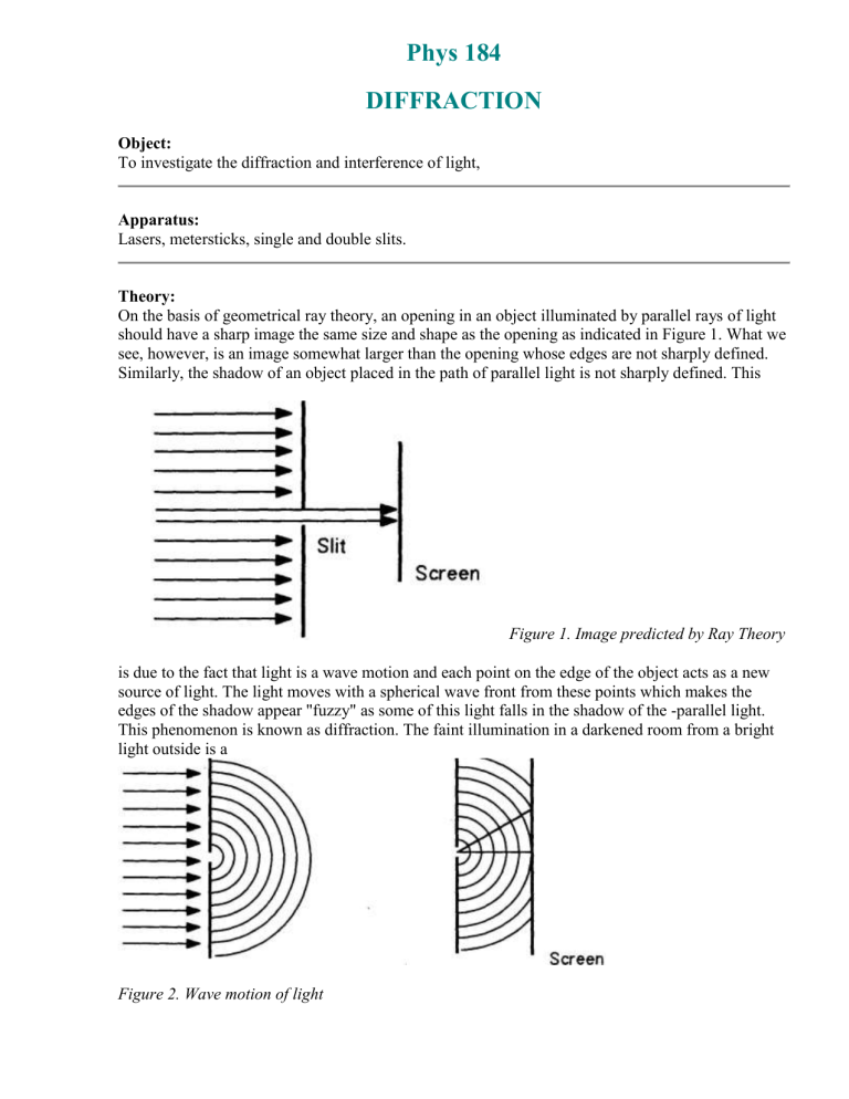
On the basis of geometrical ray theory, an opening in an object illuminated by parallel rays of light should have a sharp image the same size and shape as the opening as indicated in Figure 1. What we see, however, is an image somewhat larger than the opening whose edges are not sharply defined.
Similarly, the shadow of an object placed in the path of parallel light is not sharply defined. This
Figure 1. Image predicted by Ray Theory is due to the fact that light is a wave motion and each point on the edge of the object acts as a new source of light. The light moves with a spherical wave front from these points which makes the edges of the shadow appear "fuzzy" as some of this light falls in the shadow of the -parallel light.
This phenomenon is known as diffraction. The faint illumination in a darkened room from a bright light outside is a
Figure 2. Wave motion of light
frequently observed example of this effect The light is diffracted by the small gap at the bottom of the closed door. If a small opening or sift is illuminated, one will observe a pattern of light on a screen which consists of a central bright region flanked by alternating dark and successively dimmer regions on either side. The width of the central bright region is twice the width of the other, dimmer, regions.
Figure 3. Intensity Pattern of single slit diffraction
This is called the Fraunhofer diffraction of a single slit. Since each portion of the slit acts as a source of spherical waves (Huygen's principle), light from one portion of the slit may interfere, constructively or destructively, with that from another portion to produce the observed pattern. In
Figure 11, the circles represent crests of the spherical waves. Note that constructive interference will occur at points on the screen where the light from different parts of the slit have path lengths differing by an integral number of wavelengths. A plot of the relative intensity versus the angle of deviation for this pattern is shown- in Figure I 11. The angular position of the dark portions of this pattern is given by: n
= a sin
(Eq. 1), where
is the wavelength of the light, a is the width of the slit,
is the angular deviation, and n = 1,
2, 3 ......
If the barrier has two openings separated by a distance, d, we will also observe a pattern of equally spaced light and dark spots. The spacing of the bright spots is given by an expression similar to Eq.
1: m
= d sin
(Eq. 2), where
is the angular deviation of the bright spots and m = 1, 2, 3. Since each of the double slits is also a single slit, the patterns from the two phenomena will be superimposed. Bearing in mind that
Eq. 1 represents the positions of the minima from the single slit pattern and that Eq. 2 represents the position of the maxima from the double slit pattern, there should be points in the distribution in which the two patterns will destructively interfere with other,
designated by the lines D in figure IV. This will occur when the angles 0 and e are equal and the separation of the two slits is an integral multiple of the slit widths. This can be shown by dividing
Equation 2 by Equation 1 giving: m/n = d/a
Figure 4. Double slit interference
If the slit separation is four times the slit width, for example, destructive interference will occur when m = 4, 8, 12 . . . . The resultant pattern of intensities for the central region of a double slit is shown in Figure V. The upper curve represents the single slit pattern while the lower curve represents the distribution within the central curve. Each of the peaks in the upper curve will have a similar distribution (not shown).
Figure 5. Intensity pattern for double slit interference
Procedure and Data analysis
1 . Illuminate a 0.02 mm single slit with laser light. Record the width of the central maximum.
2. Repeat Step 1 with the 0.04 mm, 0.08 mm, and 0.16 mm slits.
3. What relationship, if any, do you observe between the slit widths and widths of the central maxima?
4. Determine the wavelength of the laser light from Equation 1, using any one of the above observations. Give the reason for your choice.
5. Illuminate each of the double slits and measure the average distance between minima. Is there any correspondence between the pattern you observe and the single slit patterns you measured?
6. Calculate the wavelength of the laser light using Equation 2. How does this agree with the calculation from Equation 1?
7. Illuminate holes of different shapes and sizes and sketch the patterns observed. Explain the process by which these patterns are formed.


