Theoretical Questions Solutions
advertisement
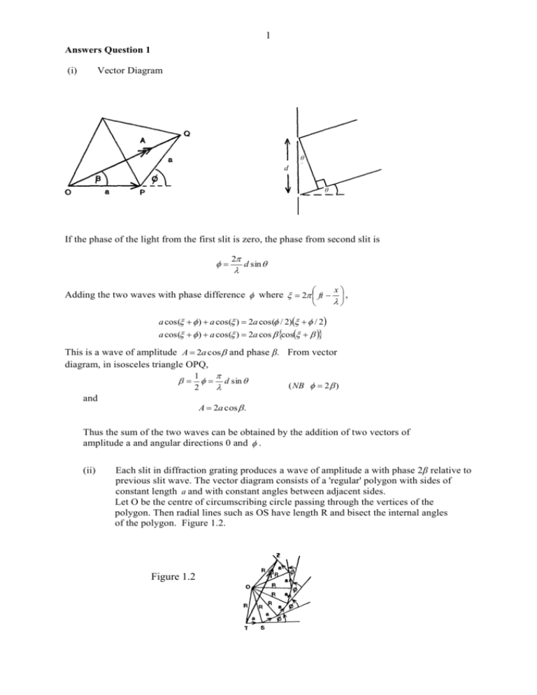
1 Answers Question 1 (i) Vector Diagram θ d θ If the phase of the light from the first slit is zero, the phase from second slit is 2 d sin x Adding the two waves with phase difference where 2 ft , a cos( ) a cos( ) 2a cos( / 2) / 2 a cos( ) a cos( ) 2a cos cos This is a wave of amplitude A 2a cos and phase β. From vector diagram, in isosceles triangle OPQ, 1 2 and d sin ( NB 2 ) A 2a cos . Thus the sum of the two waves can be obtained by the addition of two vectors of amplitude a and angular directions 0 and . (ii) Each slit in diffraction grating produces a wave of amplitude a with phase 2β relative to previous slit wave. The vector diagram consists of a 'regular' polygon with sides of constant length a and with constant angles between adjacent sides. Let O be the centre of circumscribing circle passing through the vertices of the polygon. Then radial lines such as OS have length R and bisect the internal angles of the polygon. Figure 1.2. Figure 1.2 2 ^ ^ O S T OTS 1 (180 ) 2 ^ and T OS In the triangle TOS, for example a 2R sin( / 2) 2R sin as ( 2 ) R a 2 sin (1) As the polygon has N faces then: ^ ^ T O Z N (T O Z ) N 2 N Therefore in isosceles triangle TOZ, the amplitude of the resultant wave, TZ, is given by 2R sin N . Hence form (1) this amplitude is a sin N sin Resultant phase is ^ ZT S ^ ^ OT S OT Z 1 90 180 N 2 2 1 N 1 2 ( N 1) (iii) 1 sin a sin N Intensity I β a 2 sin 2 N sin 2 3 I β 37C π 0 2π 3π (iv) For the principle maxima p where p 0 1 2........ N ' N 2 a 2 I max a 2 ' ' 0 and p ' (v) Adjacent max. estimate I1 : sin 2 N 1, 2p 3 3 i.e 2N 2N p 2 N does not give a maximum as can be observed from the graph. I1 a 2 1 3 2 2n Adjacent zero intensity occurs for For phase differences much greater than , (vi) N a2N 2 for N>>1 23 i.e. N sin N I a 2 sin a 2 . n for a principle maximum i.e. d sin n n 0,1,2.......... Differenti ating w.r.t, d cos n n d cos Substituting 589 .0nm, 589.6 nm. n 2 and d 1.2 10 6 m. n n d 1 d 2 n n as sin and cos 1 d d 5.2 10 3 rads or 0.30 0 2 4 Answers Q2 2.(i) E X Figure2.1 R θ θ O φ R X’ EX 2 R sin t 2 R sin v where v = vP for P waves and v = vS for S waves. This is valid providing X is at an angular separation less than or equal to X', the tangential ray to the liquid core. X' has an angular separation given by, from the diagram, R 2 2 cos1 C , R Thus t 2R sin , v R for cos1 C , R where v = vP for P waves and v = vS for shear waves. (ii) RC 0.5447 R vCP 0.831 .3 vP and Figure 2.2 A i E B r C Rc X θ O From Figure 2.2 ^ ^ A O C E O A (90 r ) (1 ) (1) 5 (ii) Continued Snell’s Law gives: sin i v P . sin r v CP (2) From the triangle EAO, sine rule gives RC R . sin x sin i (3) Substituting (2) and (3) into (1) v CP vP R sin i i sin 1 C sin i R 90 sin 1 (4) (iii) For Information Only For minimum , d 0 . 1 di v CP vP cos i v 1 CP sin i v P 2 RC R cos i R 1 C sin i R 2 0 Substituting i = 55.0o gives LHS=0, this verifying the minimum occurs at this value of i. Substituting i = 55.0o into (4) gives θ = 75.80. P l o t of θ a ga i n s t i . 900 75.80 550 0 900 Substituting into 4: i=0 gives θ = 90 i = 90° gives θ = 90.8° Substituting numerical values for i = 0 90° one finds a minimum value at i = 55°; the minimum values of 0, θMIN = 75•8°. 6 Physical Consequence As θ has a minimum value of 75•8° observers at position for which 2 θ <151•6° will not observe the earthquake as seismic waves are not deviated by angles of less than 151•6°. However for 2 θ 114° the direct, non-refracted, seismic waves will reach the observer. Refracted waves θ 0 R C cos 1 C R min 1800 (iv) 900 900 Using the result t 2r sin v the time delay Δt is given by 1 1 t 2 R sin vS vP Substituting the given data 1 1 131 2(6370 ) sin 6.31 10 .85 Therefore the angular separation of E and X is 2 17 .84 o RC R This result is less than 2 cos 1 3470 o 2 cos 1 114 6370 And consequently the seismic wave is not refracted through the core. 7 (v) E Y X D R R θ θ O RC The observations are most likely due to reflections from the mantle-core interface. Using the symbols given in the diagram, the time delay is given by 1 1 t ' (ED DX ) vS vP 1 1 t ' 2(ED ) as ED EX by symmetry v v P S In the triangle EYD, (ED) 2 ( R sin ) 2 ( R cos RC ) 2 (ED) 2 R 2 RC2 2 RRC cos sin 2 cos 2 1 Therefore 1 1 t ' 2 R 2 RC2 2 RRC cos v v P S Using (ii) t 2 R 2 RC 2 RRC cos R sin 396 .7 s or 6m 37s t ' Thus the subsequent time interval, produced by the reflection of seismic waves at the mantle core interface, is consistent with angular separation of 17.840. 8 Answer Q3 Equations of motion: m m m d 2 u1 dt 2 d 2u2 dt 2 d 2u3 dt 2 Substituting un (t ) u n (0) cos t and o 2 k (u 2 u1 ) k (u 3 u1 ) k (u 3 u 2 ) k (u1 u 2 ) k (u1 u 3 ) k (u 2 u 3 ) k : m (2 o 2 )u1 (0) o u 2 (0) o u 3 (0) 0 (a) o u1 (0) (2 o )u 2 (0) o u 3 (0) 0 (b) o u1 (0) o u 2 (0) (2 o )u 3 (0) 0 (c) 2 2 2 2 2 2 2 2 2 2 2 Solving for u1(0) and u2(0) in terms of u3(0) using (a) and (b) and substituting into (c) gives the equation equivalent to 2 2 (3o 2 ) 2 0 2 3 o , 3o and 0 2 3 o , 2 3 o and 0 (ii) Equation of motion of the n’th particle: d 2un k (u1 n u n ) k (u n 1 u n ) dt 2 d 2un 2 k (u1 n u n ) o (u n 1 u n ) 2 dt Substituting u n (t ) u n (0) sin 2ns cos s t N m n = 1,2……N 2 2 s sin 2ns o sin 2(n 1) s 2 sin 2ns sin 2(n 1) s N N N N 1 2 2 1 s sin 2ns 2 o sin 2(n 1) s sin 2ns sin 2(n 1) s N N N 2 N 2 2 2 s sin 2ns 2 o sin 2ns cos 2s sin 2ns N N N N 2 2 s 2 o 1 cos 2s : ( s 1,2,..... N ) N As 2 sin 2 1 cos 2 This gives s N s 2 o sin s can have values from 0 to 2 o 2 (s 1,2,... N ) k N when N ; corresponding to range s 1 to . m 2 9 (iv) For s’th mode un u n 1 un u n 1 sin 2ns N sin 2(n 1) s N sin 2ns N sin 2ns cos 2s cos 2ns sin 2s N N N N un s 1. 0, thus cos 2ns 1 and sin 2ns 0, and so N N u n 1 N (b) The highest mode, max 2 o , corresponds to s = N/2 (a) For small , Case (a) Case (b) N odd N even un sin 2n 1 1 as sin 2(n 1) u n 1 10 (vi) If m' << m, one can consider the frequency associated with m' as due to vibration of m' between two adjacent, much heavier, masses which can be considered stationary relative to m'. The normal mode frequency of m', in this approximation, is given by m‘ m m m' x 2kx '2 2k m ' 2k m' For small m', ω' will be much greater than ωmax, BAND 2ωo 0 ω ω DIATOMIC SYSTEM More light masses, m', will increase the number of frequencies in region of ω' giving a bandgap-band spectrum. BAND GAP BAND DD 0 ω

