ieee extruder d - NICADD - Northern Illinois University
advertisement
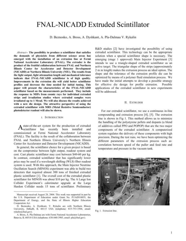
FNAL-NICADD Extruded Scintillator D. Beznosko, A. Bross, A. Dyshkant, A. Pla-Dalmau V. Rykalin Abstract-- The possibility to produce a scintillator that satisfies the demands of physicists from different science areas has emerged with the installation of an extrusion line at Fermi National Accelerator Laboratory (FNAL). The extruder is the product of the fruitful collaboration between FNAL and Northern Illinois Center for Accelerator and Detector Development (NICADD) at Northern Illinois University (NIU). The results from the light output, light attenuation length and mechanical tolerance indicate that FNAL-NICADD scintillator is of high quality. Improvements in the extrusion die will yield better scintillator profiles and decrease the time needed for initial tuning. This paper will present the characteristics of the FNAL-NICADD scintillator based on the measurements performed. They include the response to MIPs from cosmic rays for individual extruded strips and irradiation studies where extruded samples were irradiated up to 1 Mrad. We will also discuss the results achieved with a new die design. The attractive perspective of using the extruded scintillator with MRS (Metal Resistive Semiconductor) photodetector readout will also be shown. I. INTRODUCTION system for the production of extruded Astate-of-the-art scintillator has recently been installed and commissioned at Fermi National Accelerator Laboratory (FNAL). The facility is the result of the collaboration between FNAL and Northern Illinois University’s Northern Illinois Center for Accelerator and Detector Development (NICADD). In general, the scintillator choice for a given project is based on the compromise between light output, readout system and cost. Cast plastic scintillator may cost between $40-60 per kg. In contrast, extruded scintillator that has significantly lower price may be used if a wavelength shifting (WLS) fiber readout system is used. With this approach, the Main Injector Neutrino Oscillation Search (MINOS) experiment was able to build two detectors that required almost 300 tons of finished extruded plastic scintillator [1]. The overall cost of the extruded plastic scintillator for MINOS was about $10 per kg. The A Large Ion Collider Experiment’s calorimeter upgrade at the Large Hardon Collider needs 15 tons of scintillator. Preliminary Manuscript received August 28, 2004. This work was supported in part by the U.S. Department of Education under Grant No. P116Z010035, the Department of Energy, and the State of Illinois Higher Education Cooperation Act. D. Beznosko, A. Dyshkant, V. Rykalin are with Northern Illinois University, DeKalb, IL 60115 USA (telephone: 815-753-3504, email: rykalin@fnal.gov). A. Bross, A. Pla-Dalmau are with Fermi National Accelerator Laboratories, Batavia, IL 60510 USA (telephone: 630-840-3985, email: pla@fnal.gov). R&D studies [2] have investigated the possibility of using extruded scintillator. This technology can be the appropriate solution when a special scintillator shape is necessary. The emerging (stage 1 approved) Main Injector Experiment [3] intends to use a triangle-shaped extruded scintillator as an active target. The triangular shape of the strips (approximately 2 m in length) makes the extrusion process an ideal option. The shape and the tolerance of the extrusion profile die can be optimized by means of a polymer fluid simulation process. We have made the initial attempts to develop a possible strategy for effective die design for profile extrusion. Possible applications of the extruded scintillator in new experiments will be addressed. II. EXTRUDER For our extruded scintillator, we use a continuous in-line compounding and extrusion process [4], [5]. The extrusion line is shown in Fig 1. This method allows us to minimize the handling of the polystyrene pellets and dopants (a blend of additives called PPO and POPOP) that are the two major components of the extruded scintillator. A computerized system regulates the delivery of these components with high precision. During the test runs, we have been optimizing the different parameters of the extrusion process such as: correlation between speed of the puller and feed rate and temperature and pressure in the vacuum tank. Fig. 1. Extrusion line. 1 Number of strips with given width With existing dies we were able to produce scintillator strips of different shapes, some with holes for a WLS fiber and some without holes for routing the top surface as needed (Fig. 2). The presence of the co-extruded hole makes insertion of the fiber possible and saves additional expenses. Fig. 3 displays the scintillator strip with two co-extruded holes. 80 70 60 50 40 30 20 10 0 101 a) b) c) 101.1 101.2 101.3 101.4 Width, mm 101.5 Fig. 4. Histogram of the width for extruded scintillator strips. d) Fig. 2. Different shapes of extruded scintillator, all shapes shown have the coextruded hole for WLS fiber insertion. a) scintillator for MINERVA, b) scintillator for Calorimeter application with pre-shower, c) shape used in R&D studies, d) scintillator strip with up to 10 holes also used in R&D. Number of strips with given thickness 400 350 300 250 200 150 100 50 0 4.79 4.84 4.89 4.94 4.99 5.04 Thickness, mm Fig. 5. Histogram of the thickness for extruded scintillator strips. A. Optical Attenuation Length Fig. 3. Scintillator strip with two co-extruded holes. The mechanical tolerances for the width and height of the extruded scintillator profiles can be closely controlled. Measurements performed on scintillator strips extruded at Fermilab (nominal size: 100 mm wide by 5 mm thick) yielded an average width of 101.33 0.17 mm evaluated over 300 m with 50 cm interval (Fig. 4), and average thickness of 4.98 0.03 mm evaluated over 300 m with 20 cm interval (Fig. 5). Other properties of the extruded material were studied as well, such as attenuation length, light yield, uniformity of response and radiation damage. A sophisticated drying procedure with a nitrogen purging system allows the elimination of the humidity effects and the degradation of the plastic due to the presence of oxygen. The drying system and a vacuum station at the last stage of the extruder barrel improve the final optical quality of the scintillator plastic. The attenuation length was measured for the following scintillators: FNAL-NICADD extruded, K2K [6] and BC404 [7]. All pieces were cut and machined to be 2x0.5x100 cm3. All edges were polished to the same level. The co-extruded coating was removed from the K2K sample. The end furthest from the PMT was painted black and was labeled as 0cm. A PMT with a bialkali (K-Cs) photocathode was directly pressed upon the other edge, for all samples. All samples were wrapped with the same Tyvek [8] piece. A 137Cs radioactive source was placed at different distances from the PMT and the value of the PMT anode current was plotted against distance in Fig. 6 (100cm is the point closest to the PMT). 2 L2 is the fit parameter for the short component of the attenuation length of each corresponding scintillator, expressed in cm. For K2K sample, the exponent starts to rise faster than for extruded sample thus a lower value for L2 is obtained from the fit of the data for each sample. 250 BC-404 (L2=63.7cm) Response (nA) 200 K2K (L2=26.2 cm) FNAL/NICADD (L2=34.7 cm) 150 100 50 0 0 20 40 60 80 The extruded scintillator light output was also measured on 5mm thick samples (10x0.5x100 cm3 strips). A 1.2 mm outer diameter KURARAY Y-11 WLS fiber was inserted in the hole. A Metal-Resistor-Semiconductor (MRS) [10] silicon sensor with 1 mm2 photosensitive area was used for the readout. We measured ~17 photo electrons (PE) with this sensor that has quantum efficiency at 500nm of ~25% [10]. The MINOS extruded scintillator was measured for the comparison using the same 1.2mm WLS fiber. In addition, the measurements using the FNAL-NICADD extruded scintillator and 1.0mm and 1.5mm fibers were carried out. Table II summarizes the results of measurements done using the 5mm thick extruded scintillator and MRS sensor with Kuraray Y-11 WLS fibers of different diameter. Here response in PE refers to each photon detected by MRS (i.e. the total number of incident photons on the sensor is approximately the response in PE times 4). 100 Source Position (cm) TABLE II FIBER THICKNESS AND RESPONSE Fig. 6. Attenuation length for three different scintillators. All the responses are normalized at the 20 cm point to the value obtained from BC404 scintillator. B. Light Output Dopant optimization studies of the FNAL/NICADD extruded scintillator were undertaken to maximize the light output of the scintillator. The extruded scintillator is composed of polystyrene pellets (Dow Styron 663 W), 1% PPO and 0.03% POPOP. The light output was measured for the following scintillators: FNAL-NICADD extruded, BC408 [7] and Kuraray [9] SCSN-81. In this measurement, small pieces (2x0.5x2 cm3) of scintillator, wrapped in the same material, were read out by the same PMT like in the previous section, but using a 106Ru radioactive source that was always placed at the same distance from the PMT. The results are shown in Table I. Response is normalized to 1mm thickness. The results are not corrected for spectral differences in the light emission and PMT response. TABLE I SCINTILLATOR RESPONSE Type FNAL-NICADD Response (arbitrary units) 2.00.2 BC408 2.70.2 KURARAY SCSN-81 2.00.2 Fiber diameter (mm) Scintillator type and thickness Average Response (PE) 1.0 FNAL-NICADD Extruded, 5mm FNAL-NICADD Extruded, 5mm FNAL-NICADD Extruded, 5mm MINOS Extruded, 10mm 14.5 1.2 1.5 1.2 17 20.5 22.1 C. Uniformity of Response Uniformity of the response of the extruded scintillator was measured across the 10x0.5x100 cm3 strip and a hexagonal cell, with area of 9cm2 and 5mm thick. The non-uniformity of response across a scintillator strip was measured and yielded a value of ~4%. The result of a similar non-uniformity scan for the hexagonal cell is <3%. The results of these measurements are presented in Fig. 7 for the scan across the scintillating strip and in Fig. 8 for the scan across the hexagonal cell. In Fig. 7, the structure shows that response is somewhat larger near the WLS fibers, but smaller when the source is directly above and there is not as much scintillating material to produce light. The error bars are not shown because they would be on the same scale that the markers used and would not be visible. 3 In Fig. 8, the same increase is observed in the fiber region. However, because it is a groove and not a co-extruded hole, there is still enough material between the fiber and the source not to produce a slight dip in response as in the same of the extruded strips. Again, the error bars are not shown because they would be on the same scale that the markers used. place during this time period; however, the delay was due to technical reasons. The results are shown in Table III. PH is shown in arbitrary units. In addition, the transmittance of the scintillator was measured, both before and after the irradiation (see Fig. 9). As with the light yield, no significant changes were observed. 1250 80 70 1050 Transmittance (%) Response (nA) 1150 950 850 750 650 550 0 20 40 60 80 60 50 40 Before Irradiation 30 After Irradiation 20 After 85-day air anneal 10 100 Position of 90Sr, mm 0 190 290 490 590 690 790 Wavelength (nm) Fig. 7. Non-uniformity of response across the scintillator strip with two holes. Fig. 9. Transmittance of the extruded scintillator before, after and 85 days after irradiation. The slight difference in the amplitudes is within precision of the measurement. 1.2 Normalized Response 390 1 0.8 TABLE III PULSE HEIGHT BEFORE AND AFTER IRRADIATION 0.6 0.4 Dose (Mrad) 0.2 0 0 10 20 30 40 50 Position of 90Sr (mm) Fig. 8. Non-uniformity of response across the hexagonal cell. Response is normalized to the maximum value. The schematics of cell indicates the direction of scan. D. Radiation Damage Several samples of the extruded FNAL-NICADD scintillator were irradiated to 0.5 and 1 Mrad in air utilizing a 60Co gamma source with a dose rate of 0.8 Mrad per hour. Only minor degradation effects in light yield are observed, similar to the value observed in cast scintillator. Pulse height (PH) measurements were performed using a 207Bi radioactive source on scintillator discs (2 cm diameter and 1 cm thick) before and 85 days after the irradiation. Some recovery might have taken 0.5 1 Before Irradiation 2667 2736 After Irradiation 2648 2617 Light yield loss (%) none ~5 III. CONCLUSIONS The first R&D runs on the new extrusion line at FNAL have shown the attractiveness of the FNAL-NICADD scintillator for different applications in Nuclear and High Energy Physics. The mechanical tolerances are 0.6% for thickness and 0.16% for width. The scintillator response, or Light Yield (LY), is within 72% of BC408 and is equal to Kuraray SCSN-81. The LY non-uniformity is <3% for the small hexagonal cell and ~4% for the long strips. The radiation damage tests yield values for the LY degradation of <5% for 1 Mrad of gamma radiation in air and at high dose rate. No change in PH is observed with 0.5Mrad dose. 4 IV. ACKNOWLEDGMENT We thank Brian Wood (UIC) and Elena Baldina (FNAL) for their valuable help with measurements. V. REFERENCES [1] [2] A. Pla-Dalmau et al, “Extruded Plastic Scintillator for the MINOS Calorimeters”, Frascati Physics Series XXI (2000), 513-522. O.A. Grachov, T.M. Cormier, A. Pla-Dalmau, A. Bross, V. Rykalin “A Study Of New FNAL-NICADD Extruded Scintillator As Active Media Of Large EMCAL Of ALICE At LHC”, FNALCONF-04-046, XI int. Conf. Calor 2004, Italy, 2004 [3] D. Drakoulakos et al. [the MINERA collaboration], “Proposal to Perform a High-Statistics Neutrino Scattering Experiment Using a Fine-grained Detector in the NuMI Beam”. http://www.pas.rochester.edu/minerva/ A. Pla-Dalmau, A.D. Bross and V.V. Rykalin, “Extruding Plastic Scintillator at Fermilab”, IEEE Nuclear Science Symposium Conference Record Portland, OR, Oct. 19-25 2003 (FERMILAB-Conf-03-318-E). [5] A. Pla-Dalmau, A.D. Bross and K.L. Mellott, “Low-Cost Extruded Plastic Scintillator”, Nucl. Instr. Meth. A466 (2001), 482-491. [4] [6] T. Ishii, T. Inagaki, J. Breault, T. Chikamatsu, J. H. Choi, T. Hasegawa at. al., "Near Muon Range Detector for the K2K Experiment Construction and Performance", Nucl.Instrum.Meth. A482 (2002) 244253 [7] SAINT-GOBAIN (Bicron), 12345 Kinsman Road, Newbury, OH 44065, USA. [8] A. Dyshkant, D. Beznosko, G. Blazey, D. Chakraborty, K. Frances, D. Kubik et al, "Small Scintillating Cells as the Active Elements in a Digital Hadron Calorimeter for the e+e- Linear Collider Detector", FERMILAB-PUB-04/015, Feb 9, 2004 [9] Kuraray America Inc., 200 Park Ave, NY 10166,USA; 3-1-6, NIHONBASHI, CHUO-KU, TOKYO 103-8254, JAPAN. [10] V. Golovin et al., “Limited Geiger-Mode Silicone Photodode With Very High Gain:, Nucl.Phys.Proc.Suppl. 61B: 347-352, 1998. 5
